This chapter provides instructions on the wiring for:
•Model E1615
•Model E1616
•Model E1617
•Model E1618
•Automatic display shutoff
•Dual display kit
•Rate of flow switch kit
•Reset switch kit
Shielded cable for each display type - All display models |
All four display models ship with a 30-foot 4-wire shielded cable with 22-gauge wire. If alternate cabling is necessary, Liquid Controls recommends a similar 4-wire shielded cable with 22 gauge wire or larger and a maximum cable length of 30 feet. |
Connect the J1 Jumper - All display models |
All four display models ship with a jumper, which must be installed between terminal 52 and terminal 53 on the J1 terminal block of the display. During rewiring, take time to ensure that this jumper is in place. |
Wiring for Model E1615
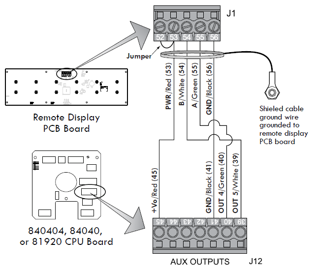
Model E1615 of the LectroCount XL LED Remote Display is designed for use with a LectroCount LCR-II or LCR 600. LectroCount LCR-II or LCR 600 electronic registers contain a 840404, 84040, or 81920 CPU board.
24 VDC Power |
If the power to the LectroCount LCR-II or LCR 600 exceeds 24 VDC, then the remote display should be powered from Pin 32 on J8, 5 VDC. |
Refer to the figure below and follow these steps to wire the LectroCount XL LED Remote Display model E1615 to a 840404, 84040, or 81920 CPU board:
1.Open the LectroCount register. Refer to the specific LectroCount Register Manual for specific instructions regarding opening, closing, and sealing the electronic register.
2.Attach a cable gland to a port on the LectroCount electronic register.
3.Route the shielded cable through the cable gland and into the LectroCount register housing.
4.Connect the four wires of the shielded cable to these terminals on the J12 terminal block on the LectroCount CPU board:
• XL LED terminal 53 (red wire) to LCR-II/600 terminal 45
• XL LED terminal 54 (white wire) to LCR-II/600 terminal 39
• XL LED terminal 55 (green wire) to LCR-II/600 terminal 40
• XL LED terminal 56 (black wire) to LCR-II/600 terminal 41
5.Tighten the cable gland and close the LectroCount register.
Wiring for Model E1616
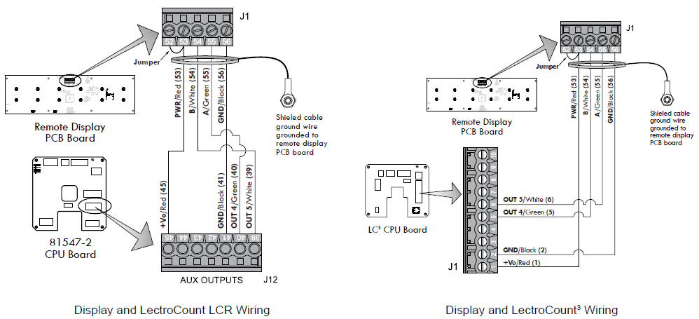
Model E1616 of the LectroCount XL LED Remote Display is designed for use with a LectroCount LCR (CPU board 81547-2) or a LC3 CPU board (Terminal Board 81924).
24 VDC Power |
If the power to the LectroCount LCR-II or LCR 600 exceeds 24 VDC, then the remote display should be powered from Pin 32 on J8, 5 VDC. |
Refer to the figure below and follow these steps to wire the LectroCount XL LED Remote Display model E1616 to a 81547-2 or LC3 CPU board:
1.Open the LectroCount register. Refer to the specific LectroCount Register manual for specific instructions regarding opening, closing, and sealing the electronic register.
2.Attach a cable gland and/or conduit connector to a port on the LectroCount electronic register.
3.Route the shielded cable through the cable gland and into the LectroCount register housing.
4.Connect the four wires of the shielded cable to these terminals on the LectroCount CPU board:
LectroCount LCR – On the J12 terminal block (81547-2), connect:
• XL LED terminal 53 (red wire) to LCR terminal 45
• XL LED terminal 54 (white wire) to LCR terminal 39
• XL LED terminal 55 (green wire) to LCR terminal 40
• XL LED terminal 56 (black wire) to LCR terminal 41
LectroCount LCR – On the J1 terminal block (81924) connect:
• XL LED terminal 53 (red wire) to LC3 terminal 1
• XL LED terminal 54 (white wire) to LC3 terminal 5
• XL LED terminal 55 (green wire) to LC3 terminal 6
• XL LED terminal 56 (black wire) to LC3 terminal
5.Tighten the cable gland and close the LectroCount register.
Wiring for Model E1617
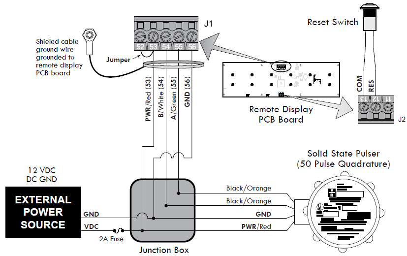
Model E1617 of the LectroCount XL LED Remote Display is designed to receive a calibrated (50 pulses per revolution) solid state quadrature pulse output. Typically, Model E1617 operates in conjunction with a solid state quadrature pulser (PN 077733) mounted onto a mechanical register using mounting kit (PN 47824).
Since quadrature pulsers do not have an output signal to reset the LED Remote Display, a Reset Switch Kit (PN 82592) is required for this application. The Reset Switch Kit resets the XL LED Remote Display to zero between deliveries. To complete the installation, the installer must provide a 12 VDC external power source and a junction box.
24 VDC Power |
If the power to the LectroCount LCR-II or LCR 600 exceeds 24 VDC, then the remote display should be powered from Pin 32 on J8, 5 VDC. |
Reversing the Display Counter Direction |
Quadrature pulse outputs can send a signal to the display to count in either direction–either up or down. If the display is counting in the wrong direction, switch the connections of signal wires from the pulser (black and orange for PN 077733) to the display (J1 terminals 54 and 55) to reverse the counter direction. |
Refer to the figure below and follow these steps to wire the LectroCount XL LED Remote Display model E1615 to a 840404, 84040, or 81920 CPU board:
1.Install Reset Switch Kit.
2.Set the junction box.
3.Route the shielded cable, the pulser wires, and the wires from the external power source into the junction box. Use the appropriate connectors.
4.Connect the shielded cable wires to the following pulser and external power source wires:
• XL LED terminal 53 (red wire) to Pulser power (red wire) to External Power Source voltage (+Vo)
• XL LED terminal 54 (white wire) to Pulser signal (black/orange wire)
• XL LED terminal 55 (green wire) to Pulser signal (black/orange wire)
• XL LED terminal 56 (black wire) to Pulser ground (white wire) to External Power Source ground
5.Tighten connectors and close the boxes.
Wiring for Model E1618 - LCMag™
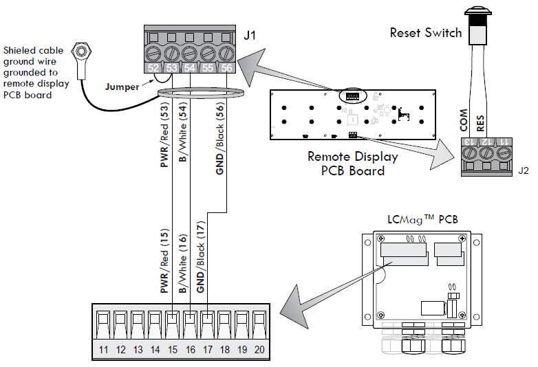
Model E1618 of the LectroCount XL LED Remote Display will accept the calibrated pulse output of the LCMag HML210 converter.
Since the HML210 does not have an output signal to reset the LED Remote Display, a Reset Switch Kit (PN 82592) is required for this application. The Reset Switch Kit resets the XL LED Remote Display to zero between deliveries.
Refer to the figure below and follow these steps to wire the LectroCount XL LED Remote Display model E1618 to the HM L210 Converter:
1.Install Reset Switch Kit.
2.Open the LCMag HML210 converter. Refer to manual IEM200-10 for specific instructions regarding opening, closing, and sealing the converter.
3.Route the shielded cable through a cable gland and into the HML210 housing.
4.Connect the shielded cable wire to the designated terminals on the HML210 CPU board:
• XL LED terminal 53 (red wire) to LCR-II/600 terminal 45
• XL LED terminal 54 (white wire) to LCR-II/600 terminal 39
• XL LED terminal 55 (green wire) to LCR-II/600 terminal 40
• XL LED terminal 56 (black wire) to LCR-II/600 terminal 41
5.Tighten the cable gland and close the HML210 converter.
Wiring for Model E1618 - Single Channel Pulsers
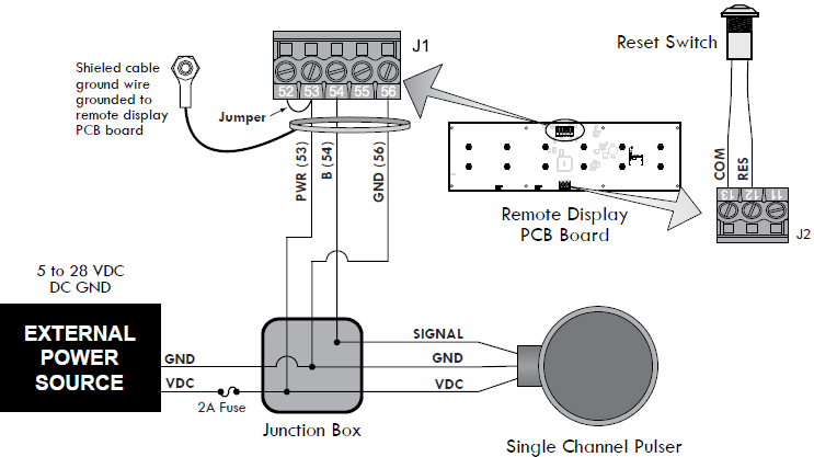
Model E1618 of the LectroCount XL LED Remote Display is designed to receive a calibrated single channel pulse output. A common application of Model E1618 is with a 100 pulses per revolution solid state single channel pulser (PN 07525) mounted onto a mechanical register using mounting kit (PN 42695). The E1618 is also compatible with any single channel pulser that meets the required specifications listed below.
Since single channel pulsers do not have an output signal to reset the LED Remote Display, a Reset Switch Kit (PN 82592) is required for this application. The Reset Switch Kit resets the XL LED Remote Display to zero between deliveries. To complete the installation, the installer must provide a 5 to 28 VDC external power source and a junction box.
Refer to the figure below and follow these steps to wire the LectroCount XL LED Remote Display model E1618 to a single channel pulser:
1.Install Reset Switch Kit.
2.Set the junction box.
3.Route the shielded cable, the pulser wires, and the wires from the external power source into the junction box. Use the appropriate connectors.
4.Connect the shielded cable wires to the following pulser and external power source wires:
• XL LED terminal 53 (red wire) to Pulser power (red wire) to External Power Source voltage (+Vo)
• XL LED terminal 54 (white wire) to Pulser signal
• XL LED terminal 56 (black wire) to Pulser ground (white wire) to External Power Source ground
5.Tighten connectors and close the boxes.
Specifications for Single Channel Pulsers |
|
Single Channel Pulse Device |
•Solid State |
Signal Level |
•≥ 2.50 VDC high •≤ 2.00 VDC low |
Output |
•1.5 mA sinking |
Frequency |
•5 kHz maximum |
Wiring for the Automatic Shutoff
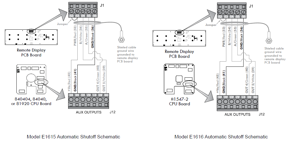
The LectroCount XL LED Remote Display can be wired to turn on and shut off automatically. If wired for automatic shutoff, the display will automatically turn on when a delivery is initiated. The display will remain lit until a delivery ticket is printed. When the delivery ticket begins printing, the display will automatically shut off. Only models E1615 and E1616 can be wired for automatic shutoff.
Refer to the figure below and follow these steps to wire the LectroCount XL LED Remote Display for automatic shutoff:
1.Connect the power and two signal wires.
2.Instead of connecting the black (GND) wire to terminal 41 on the J12 terminal block, connect the black (GND) wire to terminal 44 of the J12 terminal block on the LectroCount register CPU board.
Wiring for Dual Displays
The dual display kit allows two LectroCount XL LED Remote Displays to display the delivery volume of a single
LectroCount electronic register.
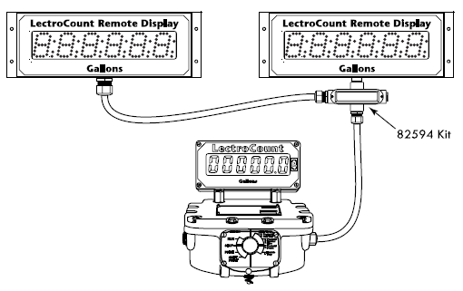
This dual display kit includes:
•4-port conduit box
•Cord grip (2)
•Nipple & seal washer
Secure cable and tighten cover upon reassembly |
LectroCount XL LED Remote Displays ship ready for final cable termination. If the pre-installed shielded cable is removed during installation, be sure to secure the cable and tighten the cover so the vapor seal remains intact. |
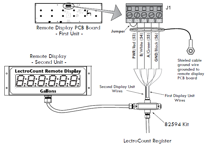
Refer to the figure below and follow these steps to install the dual display kit:
1.Remove the rear panel from one LectroCount XL LED Remote Display.
2.Remove the cable wires from the J1 terminal block on the PCB.
3.Remove the cord grip and cable from the port on the bottom of the unit.
4.Attach the 4-port conduit box to the empty port on the bottom of the unit.
5.Attach the cord grips to the 4-port conduit box.
6.Route the shielded cable from the second LectroCount XL LED Remote Display through one of the cord grips on the 4-port conduit box.
7.Route the shielded cable from the first LectroCount XL LED Remote Display through the other cord grip on the 4- port conduit box.
8.Connect the wires from both shielded cables to the J1 terminal block on the PCB of the first LectroCount XL LED Remote Display.
9.Replace the rear panel of the display.
10.Connect the cable wires from the first LectroCount XL LED Remote Display to the LectroCount electronic register CPU board.
Wiring for the Rate of Flow Switch Kit
The dual display kit allows two LectroCount XL LED Remote Displays to display the delivery volume of a single LectroCount electronic register.
For Model E1615 Only |
The Rate of Flow Switch Kit is compatible with LectroCount LCR-II and LCR 600 electronic registers only. |
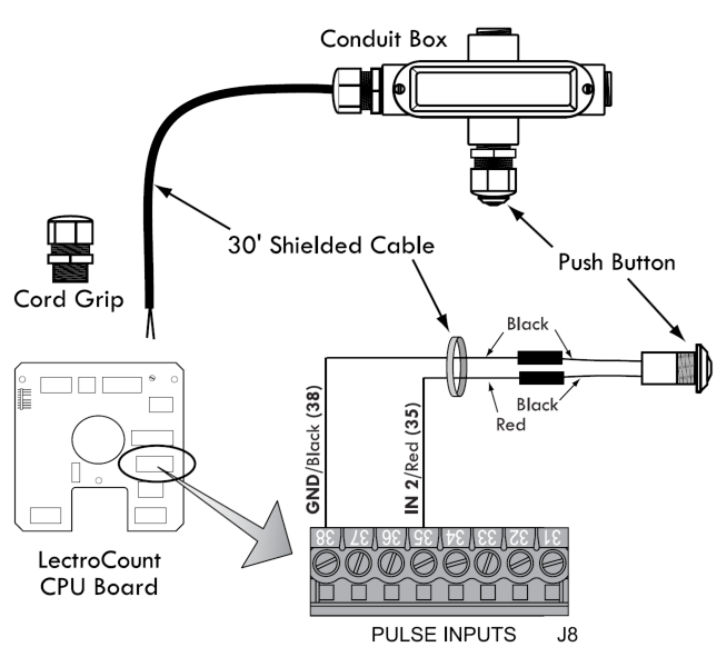
The Rate of Flow Switch Kit is an optional accessory that toggles the LectroCount XL LED Remote Display from the delivery volume to the current flow rate. To toggle to the current flow rate display, push the button. After five seconds, the display will return to the delivery volume. The select switch kit includes:
•Push button (w/ cord grip)
•Cord grip (2)
•4-port conduit box
•30-foot, 2-wire, shielded cable
The switch kit accessory connects directly to a LectroCount LCR-II or LCR 600.
LCR 600 Software Requirements |
To function with an LCR 600, the Rate of Flow Switch Kit must be wired to a 840404 CPU board flashed with version 2.12 or higher of the SR600 firmware. |
Follow these steps to install the Rate of Flow Switch Kit:
1.Determine the best location for the push button.
2.Mount the conduit box at the determined location.
3.Screw a cord grip into the conduit box and a port in the LectroCount register.
4.Route the 30-foot shielded cable through the cord grips in the conduit box and the LectroCount register and tighten the cord grips.
5.Screw the push button into the conduit box and connect the push button wires to the cable wires.
6.Connect the 30-foot shielded cable’s red wire to terminal 35 and black wire to terminal 38 on the J8 terminal block on the LectroCount CPU board.
Secure Cable and Tighten Cover Upon Reassembly |
LectroCount XL LED Remote Displays are assembled and shipped ready for final cable termination. If the pre-installed shielded cable is removed during installation, be sure to secure the cable and tighten the cover so the vapor seal is maintained. See Torque Specifications. |
Wiring the Reset Switch Kit (PN 82592) - Models E1617 & E1618
The Reset Switch Kit (P. N. 82592) is required for the installation of XL LED Remote Display models E1617 and E1618. The reset switch resets the XL LED Remote Display to zero between deliveries.
The reset switch can not zero out the totalizer while a delivery is active. To zero the display totalizer, the reset switch must be pushed when the display is not receiving a pulse output. The switch must be pushed and held for two seconds before the display will reset to zero.
The Reset Switch Kit includes:
•½", 4-port conduit box (2)
•Port plugs (2)
•Cord grips (3)
•Reset switch
•Nipple
•30-foot shielded cable
Follow these steps to install the Rate of Flow Switch Kit:
1.Determine the best location for the push button.
2.Mount the conduit box at the determined location.
3.Attach a 4-port conduit box to the empty port on the bottom of the unit.
4.If mounting the reset switch directly to the XL LED Display, screw the reset switch into a port on the 4-port conduit box.
5.If mounting the reset switch remotely, mount the second 4-port conduit box and screw the reset switch into a port on the second 4-port conduit box.
6.Screw the cord grips into the conduit box(es). Use diagrams below to determine the best ports for cord grips.
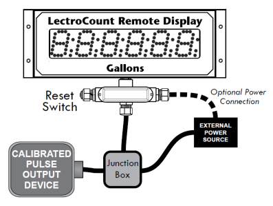 |
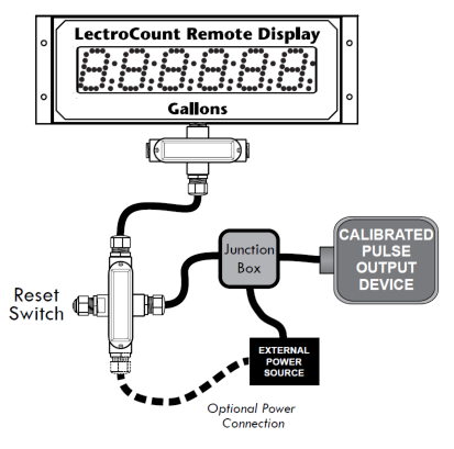 |
7.Route the 30-foot shielded cable (supplied with the reset switch kit) from the reset switch through the conduit box(es) into the XL LED Remote Display housing.
8.Connect the shielded cable wires to the reset switch inside its conduit box and to terminals 12 and 13 on the J2 terminal block on the XL LED Remote Display PCB.
9.Route the shielded cable (supplied with the XL LED Remote Display) out of the display housing and through the conduit box(es).
10. Replace the rear panel of the display. See Torque Specifications.
11. Install and wire the calibrated pulse output device according to the instructions in the sections above.
Secure Cable and Tighten Cover Upon Reassembly |
LectroCount XL LED Remote Displays are assembled and shipped ready for final cable termination. If the pre-installed shielded cable is removed during installation, be sure to secure the cable and tighten the cover so the vapor seal is maintained. See Torque Specifications. |
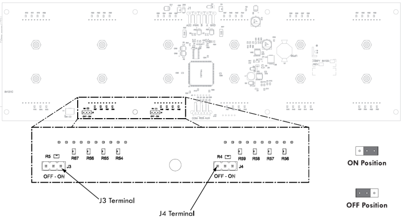
Decimal Place Jumper Setting - Model E1616
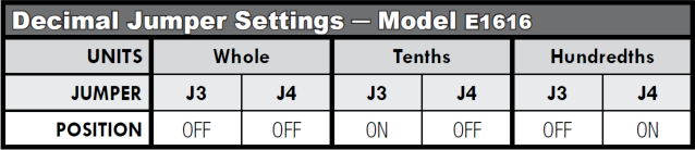
The decimal place setting of model E1616 LectroCount XL LED Remote Displays is determined by the position of jumpers on the J3 and J4 terminals on the PCB. The terminals are located on the bottom of the PCB on the left side.
For Model E1616 Only |
The decimal place displayed on Model E1615 coincides with the LectroCount LCR-II/LCR 600 decimal place setting and does not require positioning of the jumpers. |
To set the decimal place of Model E1616 LectroCount XL LED Remote Displays:
1.Remove the rear panel of the display.
2.Slide the J3 and J4 jumpers over the terminal pins in the desired position. see table below.
Jumpers Must Be on Terminal Pins: Do not remove and discard jumpers. The absence of a jumper does not qualify as the OFF position. If whole units are desired, J3 and J4 must both have a jumper in the OFF position.
J3 and J4 cannot both be in the ON position: If this is the case, two decimal points will appear on the display. This is not a valid jumper configuration.
3.Replace the rear panel of the display. See Torque Specifications.
Secure Cable and Tighten Cover Upon Reassembly |
LectroCount XL LED Remote Displays are assembled and shipped ready for final cable termination. If the pre-installed shielded cable is removed during installation, be sure to secure the cable and tighten the cover so the vapor seal is maintained. See Torque Specifications. |