 |
WARNINGFor North American Installations, the installation must be done in full accordance with the National Electrical Code (US)–or the Canadian Electrical Code–to maintain the hazardous location ratings on the product. |
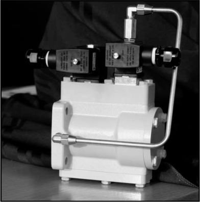
Prior to installing the cables between the solenoids and the LectroCount register, determine the orientation of the solenoids that will be the best for installation. Both solenoids have a cable connector which can be rotated in 90° increments–providing four options for orientation. Choose any orientation in which the solenoid is not upside down.
Follow the steps below to wire the solenoids to the register.
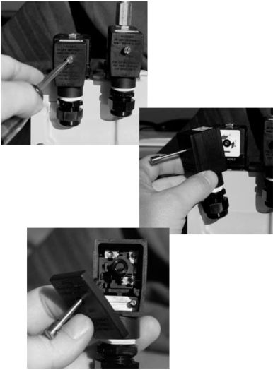
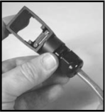
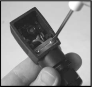
Step 1Using a flat screw driver, loosen the screw on the cable connector cover.
Remove the cable connector from the solenoid.
Remove the cover and screw from the cable connector. |
|
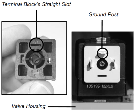
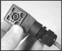
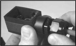
Note the markings on the back of the terminal block. To connect the cable connector to the solenoid valve, the straight slot of the terminal block must be positioned so it is the female to the male of the ground post on the solenoid valve. Both must be positioned farthest from the valve housing. To change the cable connectors orientation in relation to the valve, rotate and reinsert the terminal block into the cable connector. |
|
Step 2Remove the terminal block from the back of the cable connector.
|
|
Step 3Feed one end of the cable through the cable gland of the cable connector.
|
|
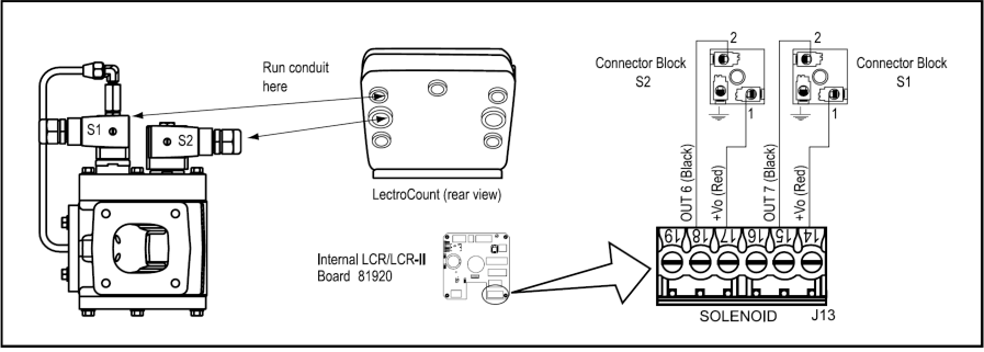
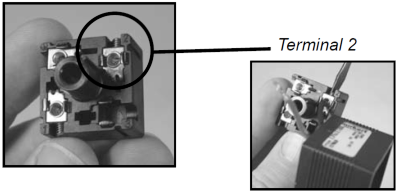
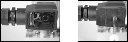
Step 4Connect the black wire to terminal 2 and tighten with a flat blade screwdriver.
NOTE: The correct terminals can be identified by raised plastic numbers beside each terminal.
|
|
Step 5Connect the red wire to terminal 1 and tighten with a flat blade screwdriver.
|
|
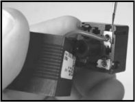
Step 6Rotate the terminal block to the desired orientation and then put back into place. In the picture to the right, the straight slot is orientated so that the cable connector will point to the side of the valve.
|
|
Step 7Tighten the retention clamp on the inside of the connector housing using a screwdriver. |
|
Step 8Tighten the cable gland around the cable. |
|
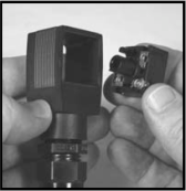
Step 9Plug the connector back into the solenoid. If the cable is not pointing in the desired direction, unplug the cable connector, take out the terminal block, rotate to the desired orientation, and then place the terminal block back in place. |
|
Step 10Place the cover over the cable connector and screw in place.
Step 11Repeat steps 1 through 12 for the second cable connector.
Step 12Proceed with routing the cables to the back of the LectroCount register. Refer to Publication Number 500301, “Installation Manual - LectroCount LCR-II Electronic Register” for detailed instructions on wiring the E-7 valve to the LectroCount. A wiring diagram for this connection is also provided below. |
|