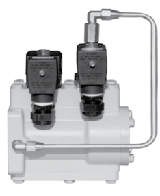
This section covers complete disassembly and reassembly of the E-7 valve. Complete disassembly is often unnecessary when performing maintenance or troubleshooting on the valve. Most components are removable without removing the valve from the meter.
 |
SAFELY EVACUATE PIPING SYSTEMBefore disassembly of any meter or accessory component: ALL INTERNAL PRESSURES MUST BE RELIEVED AND ALL LIQUID DRAINED FROM THE SYSTEM IN ACCORDANCE WITH ALL APPLICABLE PROCEDURES.
•Pressure must be 0 (zero) psi. •Close all liquid and vapor lines between the meter and liquid source.
Failure to follow this warning could result in property damage, personal injury, or death from fire and/or explosion, or other hazards that may be associated with this type of equipment. |
Disassembling the Valve
Follow the steps below to disassemble the valve.
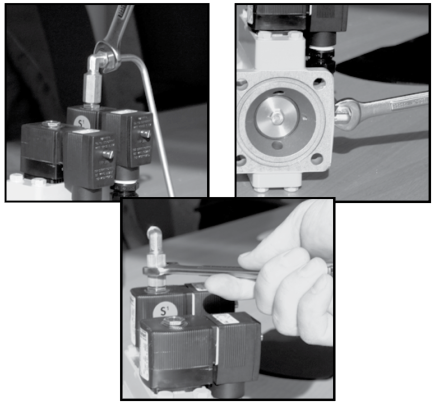
Step 1 - Remove the S1 Bypass TubingUsing an 9/16-inch wrench, loosen the two fittings on each end of the bypass tubing. Remove the tubing and set aside. Then, remove the fitting from the top of the S1 solenoid. |
|
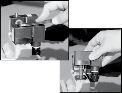
Step 2 - Remove the S1 and S2 SolenoidsUsing an 9/16-inch wrench, remove the nuts on top of the S1 and S2 solenoids, and then lift the solenoid coils off their post. |
|
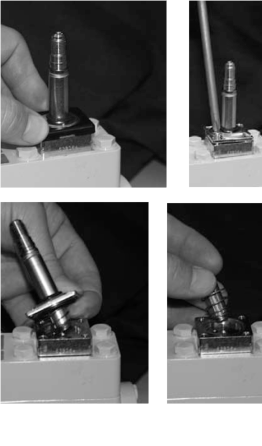
Step 3 - Remove the S1 Solenoid Guide PostRemove the plastic bonnet from the base. Next, remove the two Torx head screws threaded into the solenoid base. Then, remove the Phillips head screws threaded into the solenoid manifold.
When pulling the post from the base, be sure to catch the spring and poppet as they slip from the inside of the guide post cylinder.
If there is no need to inspect the spring and poppet of the guide post assembly, the base and the guide post can be removed from the solenoid manifold as a single unit. Simply remove the long Phillips screws and remove the base and guide post.
|
 |
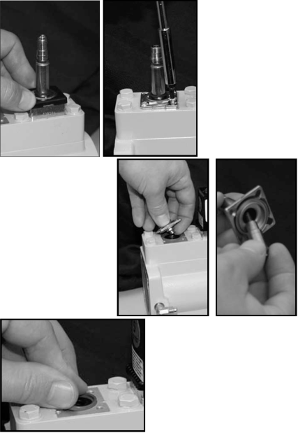
Step 4 - Remove the S2 Solenoid Guide PostUsing a Torx screwdriver, remove the four screws which hold the guide post in place. Then, lift the guide post off of the valve.
When pulling the post from the base, be sure to catch the spring and poppet as they slip from inside of the guide post cylinder.
Remove the diaphragm from the hole in the solenoid manifold.
NOTE: Be careful not to puncture the diaphagm if you use a tool to loosen it from the manifold hole. |
|
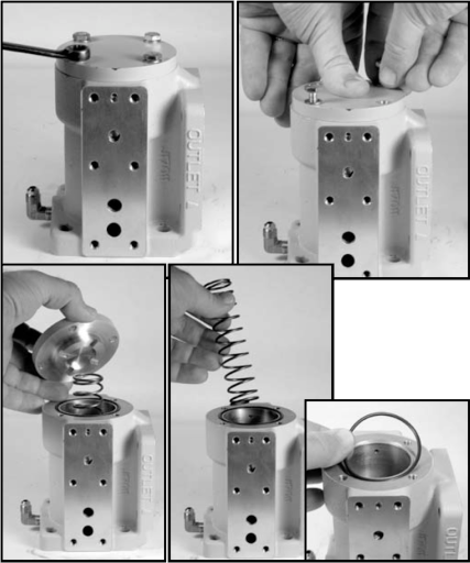
Step 5 - Remove the Piston Cover PlateUsing a 7/16-inch wrench, loosen the four screws which hold the cover plate on the back end of the valve. Behind the cover plate is a spring. Hold the cover plate down with one hand before removing the four screws completely.
When the four screws have been removed, allow the spring to completely expand and relax before removing the cover plate.
Remove the spring from the valve. The piston will remain in the valve. Remove and inspect the O-ring. Replace if necessary.
|
|
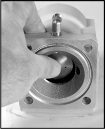
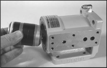
Step 6 - Remove the PistonTo remove the piston from the valve body, lay the valve on its side. Push the piston out from the front end and pull it out from the valve body from the back end. |
|
Service TipWhen the valve is service in the vehicle, a slight vacuum will be created when removing the piston from the valve.
The fastener which holds the piston O-ring washer was left long so that a long nose pliers can be used to aid in removal of the piston.
|
|
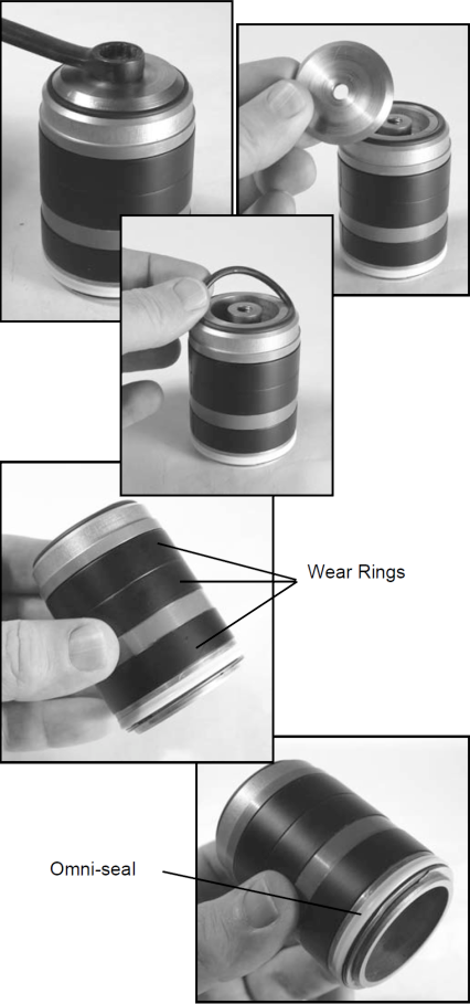
Step 7 - Disassemble the PistonUse a 7/16” wrench to remove the screw which holds the piston washer and O-ring in place. When the screw is removed, the piston washer is removed and then the O-ring.
Inspect the O-ring and replace as needed. Check the wear rings. If they show signs of excessive wear, replace them with new wear rings. Check the Omniseal ® and replace if it shows signs of wear.
|
|
Reassembling the Valve
Follow the steps below to disassemble the valve.
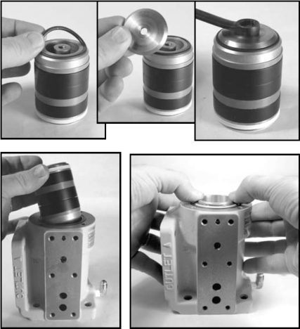
Step 1 - Assemble the PistonUse a 7/16-inch wrench to remove the screw which holds the piston washer and O-ring in place. When the screw is removed, the piston washer is removed and then the O-ring.
Inspect the O-ring and replace, as necessary. Check the wear rings. If they show signs of excessive wear, replace them with new wear rings. Check the Omniseal® and replace if it shows signs of wear.
|
|
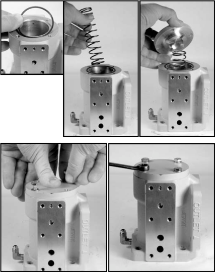
Step 2 - Replace the Piston Cover PlatePlace the O-ring in the groove in the valve housing. Insert the spring into the center of the piston. Place the cover on the spring and compress. Insert the four screws and tighten by hand, holding the cover plate in place. Tighten the four screws using a 7/16-inch wrench.
|
|
Step 3 - Replace the Valve PlateThe valve body is symmetrical with respect to the placement of the valve plate and the solenoid manifold. Select the side of the valve which provides for the most convenient orientation, taking into consideration the valve inlet, outlet, and solenoid location.
The valve plate is not symmetrical with respect to its placement on the valve. The center holes are offset. The figures to the right show the difference if the plate is rotated 180° out of proper orientation. The center holes of the valve will not line up with the center holes of the plate. It is important to install in the proper orientation so that all six screws and washers are used. |
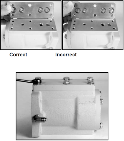
|
Insert the six screws and washer and fasten with a 7/16-inch wrench. The six screws for this plate are the shorter of the set of six screws. |
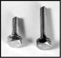
|
Step 4 - Install the Solenoid ManifoldLike the valve plate, the solenoid manifold must be installed in the proper orientation to ensure the proper alignment of the porting.
Place the solenoid manifold on the valve body and insert the six longer screws and washers fasten with a 7/16-inch wrench.
|
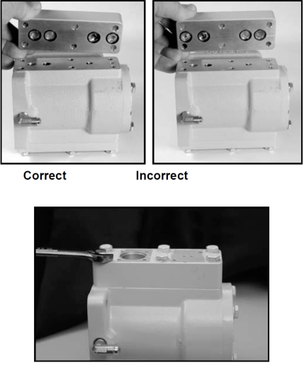
|
Step 5 - Install the S2 Solenoid PostReplace the diaphragm into the large hole on the top of the solenoid manifold.
Assemble the guide post, poppet and spring. Put the spring in the hole on the top of the poppet. Push the poppet, spring first, into the guide post, Place the guide post assembly into the diaphragm, poppet first and hold while starting the screws.
Tighten the assembly to the manifold using a Torx screwdriver. Place the plastic bonnet over the metal base.
|
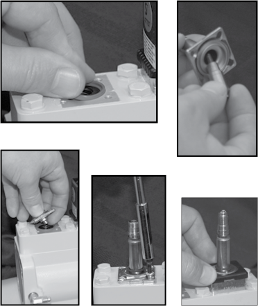
|
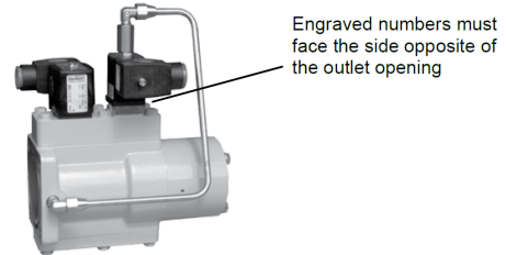
Step 6 - Install the S1 SolenoidPlace the S1 base onto the manifold so the the engraved numbers face the side opposite the outlet opening.
NOTE: The S1 solenoid will NOT operate if it is oriented incorrectly. |
|
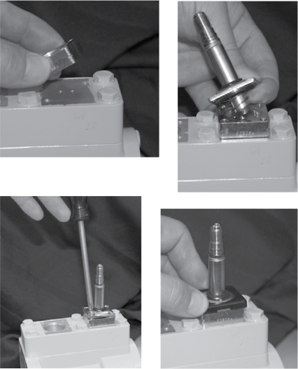
Assemble the poppet and spring into the guide post. The wide end of the spring loosely fits into the bottom of the guide. The narrow end of the poppet should face down and away from the guide post. Compressing the spring should move the poppet in and out of the guide post.
Place the guide post assembly, the narrow end of the poppet first, over the base. Hold both to the solenoid manifold and start the two long Phillps screws into the threaded holes of the manifold.
Tighten the two Torx screws and the two Phillips screws. Reattach the plastic bonnet to the base
|
|
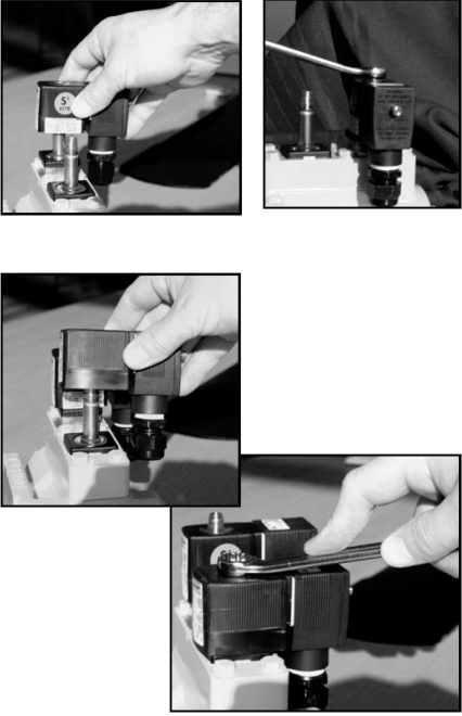
Step 7 - Install the S1 and S2 SolenoidPlace the solenoid coils over the posts, then replace the nuts and tighten with an 9/16-inch wrench.
|
|
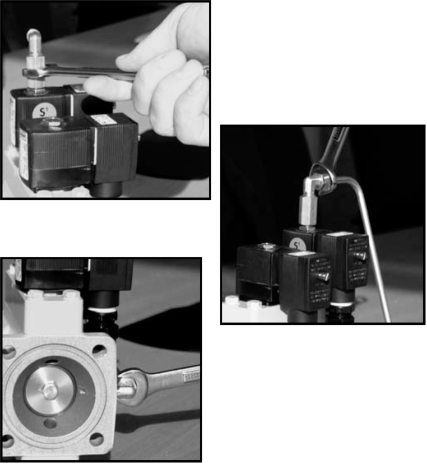
Step 8 - Install the Bypass TubingInstall the bypass tubing so that there is no tension and the fittings attach with ease. If this is not the case, adjust the elbow fitting on the S1 solenoid.
Tighten the fittings using an 9/16-inch wrench. |
|
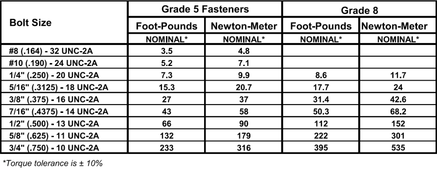
Torque Chart