Analog Inputs with SENSEiQ™ I/O Expansion Board
The SENSEiQ board has six 4-20 mA current loop inputs. These inputs can accommodate loop powered sensors–or sensors that require separate DC power connections.
Examples of analog input sensors include:
•Water detection sensors
•Tank level sensors
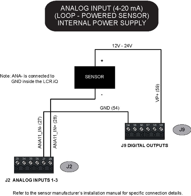
SENSEiQ™ Analog Input – Loop Powered Sensor Using Onboard DC Power
The diagram below shows how to connect a loop-powered sensor to a 4-20 mA analog input channel, using the voltage available from the register power bus.
Use the Digital Output terminal block to obtain DC power for the sensor. Voltage on the +VP terminal will be the same as the register power supply voltage.
For specific connection details, refer to installation manual from the sensor manufacturer.
Use a 12V power supply |
Do not connect a sensor rated for +12V to a register operating from a +24 V power supply. Use a separate +12V DC power supply to properly operate the sensor. |
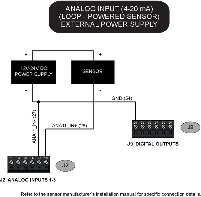
SENSEiQ™ Analog Input- Loop-Powered Sensor with External Power Supply:
The diagram below shows how to connect a loop- powered sensor to a 4-20 mA analog input channel, using an external DC power supply.
For specific connection details, refer to installation manual from the sensor manufacturer.
NOTES |
1.Use an external DC power supply with the proper rating for the sensor. 2.Connect the ground wire as shown to make a stable voltage reference. |
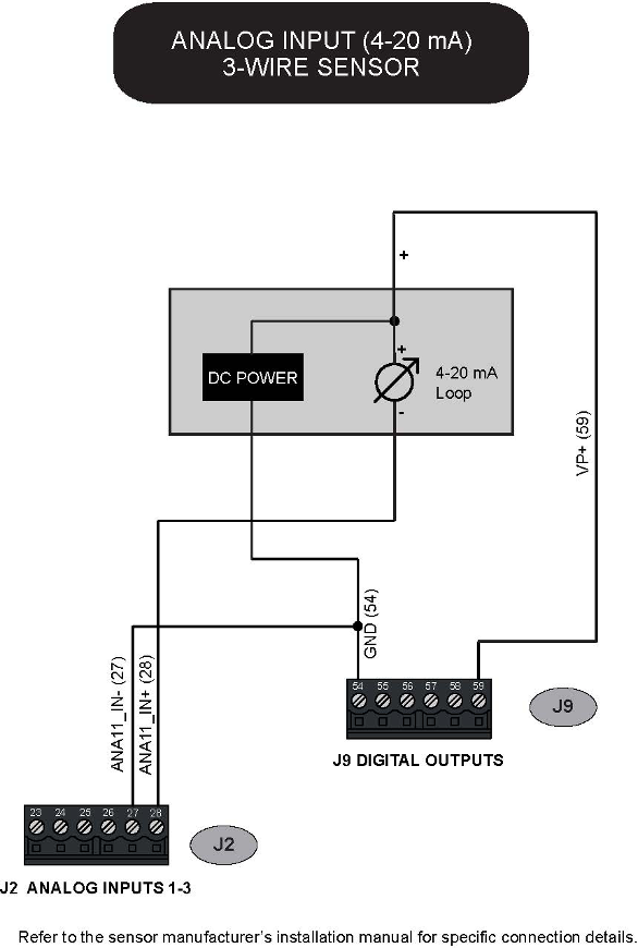
SENSEiQ™ Analog Input – 3-wire sensor
The diagram below shows how to connect a 3-wire sensor to a 4-20 mA analog input channel, using the voltage available from the register power bus.
Use the Digital Output terminal block to obtain DC power for the sensor. Voltage on the +VP terminal will be the same as the register power supply voltage.
For specific connection details, refer to installation manual from the sensor manufacturer.
Use a 12V power supply |
Do not connect a sensor rated for +12V to a register operating from a +24 V power supply. Use a separate +12V DC power supply to properly operate the sensor. |
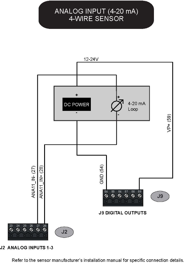
SENSEiQ™ Analog Input – 4-wire sensor
The diagram below shows how to connect a 4-wire sensor to a 4-20 mA analog input channel, using the voltage available from the register power bus.
Use the Digital Output terminal block to obtain DC power for the sensor. Voltage on the +VP terminal will be the same as the register power supply voltage.
For specific connection details, refer to installation manual from the sensor manufacturer.
Use a 12V power supply |
Do not connect a sensor rated for +12V to a register operating from a +24 V power supply. Use a separate +12V DC power supply to properly operate the sensor. |
Wiring Diagram
Download a full-size, high-resolution PDF of the wiring diagram.