Digital Inputs
LCR.iQ digital inputs are active-low, which means the input signal is normally high unless it is forced low by an external device.
Each digital input is pulled high through a 2200-ohm resistor to supply voltage.
Devices connected to an LCR.iQ digital input must be able to sink the following current:
•18 mA for 24-volt electrical systems
•7.3 mA for 12-volt electrical systems
Examples of external devices include:
•Input pulser channels (pulse train signals, up to 10 kHz).
•Optical Air Eliminator sensor (output low when no air present). Any device which sets an output to ground, such as a relay or solid-state switch.
Solid-state switches may be either of the "totem-pole" or "open drain" type.
 |
WARNINGAlthough the digital input signal lines contain protection against high-voltage transients, an active signal should not exceed the main supply voltage value. |
Digital Input 7 |
Digital Input 7 is reserved for low-speed signals as used by Liquid Controls optical Air/Vapor eliminator. |
Digital Outputs
LCR.iQ digital outputs are ‘active-low open drain’, which means the output signal is normally high. The digital outputs provide a path to ground for devices powered by the systems supply voltage.
Each digital output is pulled high by an internal resistor. This provides a method to check for proper operation of a digital output with no load attached. Connecting a voltmeter to the desired port and ground will verify proper operation of the digital output:
•If the voltage is high (vehicle battery), the output is inactive.
•If the voltage is low (less than 1 volt), the output is active.
Each digital output contains a diode clamp, so connecting inductive loads (such as relay coils or solenoids) will not damage the register electronics.
Each digital output is also protected against accidental faults to battery or ground. If a fault occurs, the output shuts down automatically. The output resumes normal operation after clearing the fault.
Examples of digital outputs include:
•Calibrated Pulse Output – Select the desired digital output line (D-OUT-1 through D-OUT-6) and desired scale factor.
•Liquid Controls XL Display (E1615) – Set two of the digial outputs (D-OUT-1 through D-OUT-6) to LC Display A and LC Display B when utilizing the XL Displays digital signal. Both channels A and B are required for operation.
•Relay coil – to control high-current loads.
Solenoid Outputs
LCR.iQ solenoid outputs are active-low open drain, which means the output signal is normally high. The solenoid outputs provide a path to ground for devices powered by the systems supply voltage.
Each solenoid output is pulled high by an internal resistor. This provides a method to check for proper operation of a solenoid output with no load attached. Connecting a voltmeter to the desired port and ground will verify proper operation of the digital output:
•If the voltage is high (vehicle battery), the output is inactive.
•If the voltage is low (less than 1 volt), the output is active.
Each digital output contains a diode clamp, so connecting inductive loads (such as relay coils or solenoids) will not damage the register electronics.
Each solenoid output is also protected against accidental faults to battery or ground. If a fault occurs, the output shuts down automatically. The output resumes normal operation after clearing the fault.
Examples of solenoid outputs include:
•Single stage and Two stage valve control solenoids
•Vapor purge valve solenoids for optical Air Elimination
Analog Input (LCR.iQ)
The LCR.iQ register has one 4-20 mA current loop input. This input can accommodate loop powered sensors, or sensors that require separate DC power connections.
Examples of analog input sensors include:
•Water detection in fuel
•Tank level (Near Future)
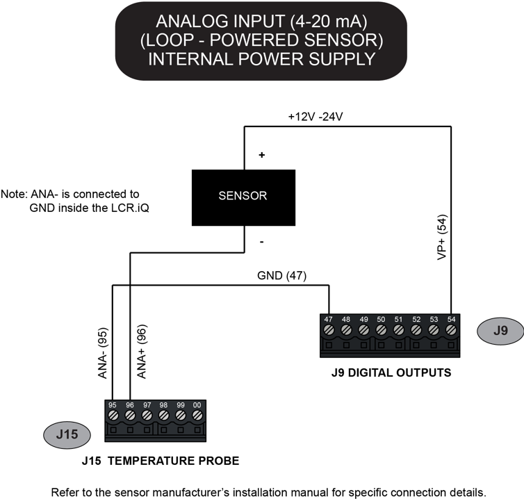
LCR.iQ Analog Input – Loop Powered Sensor using Onboard DC Power
The diagram shows how to connect a loop-powered sensor to a 4-20 mA analog input channel, using the voltage available from the register power bus.
Use the Digital Output terminal block to obtain DC power for the sensor. Voltage on the +VP terminal will be the same as the register power supply voltage. See the diagram below. Refer to the sensor manufacturer’s installation manual for specific connection details.
|
WARNINGDo not connect a sensor rated for +12V to a register operating from a +24 V power supply. Use a separate +12V DC power supply to properly operate the sensor. |
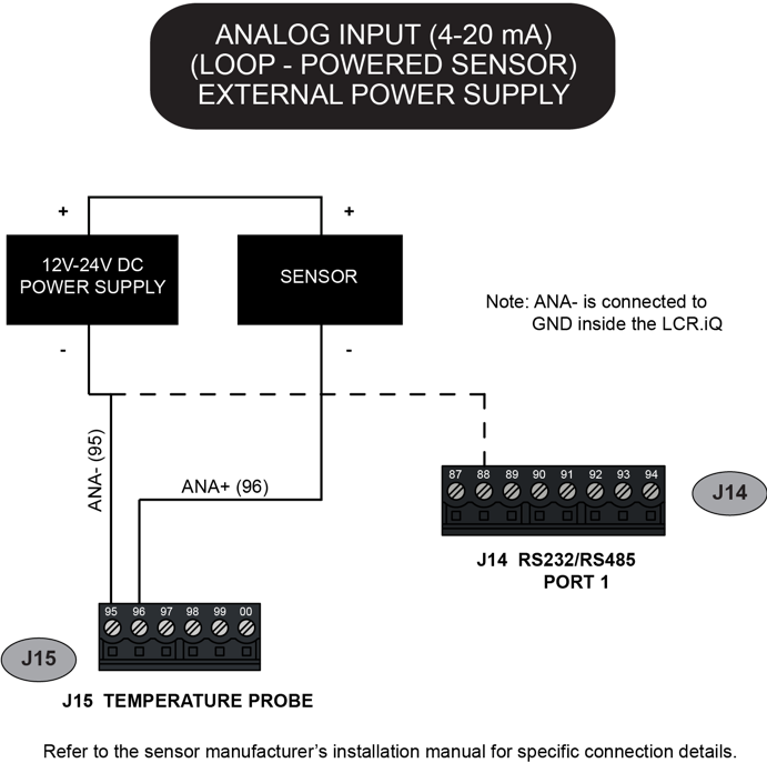
LCR.iQ Analog Input- Loop-Powered Sensor with External Power Supply
The diagram below shows how to connect a loop- powered sensor to a 4-20 mA analog input channel, using an external DC power supply. Refer to the sensor manufacturer’s installation manual for specific connection details.
Power Supply Rating |
Use an external DC power supply with the proper rating for the sensor. Connect the ground wire as shown in the diagram below to make a stable voltage reference. |
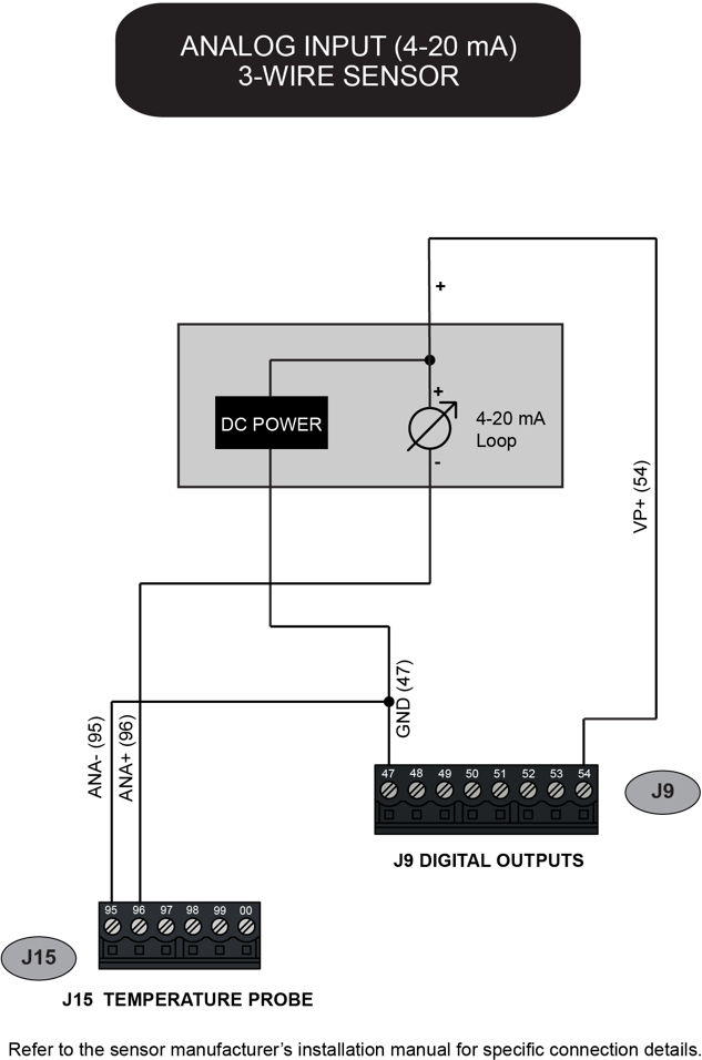
LCR.iQ Analog Input – 3-Wire Sensor
The diagram shows how to connect a three-wire sensor to a 4-20 mA analog input channel, with DC power provided by the register.
Use the Digital Output terminal block to obtain DC power for the sensor. Voltage on the +VP terminal will be the same as the register power supply voltage. Refer to the sensor manufacturer’s installation manual for specific connection details.
|
WARNINGDo not connect a sensor rated for +12V to a register operating from a +24 V power supply. Use a separate +12V DC power supply to properly operate the sensor. |
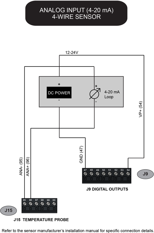
LCR.iQ Analog Input – 4-Wire Sensor
The diagram shows how to connect a four-wire sensor to a 4-20 mA analog input channel, with DC power provided by the register.
Use the Digital Output terminal block to obtain DC power for the sensor. Voltage on the +VP terminal will be the same as the register power supply voltage. Refer to the sensor manufacturer’s installation manual for specific connection details.
|
WARNINGDo not connect a sensor rated for +12V to a register operating from a +24 V power supply. Use a separate +12V DC power supply to properly operate the sensor. |