Reassembling the Meter includes the following:
•Reassembling the bearing plates and rotors
•Timing the rotor gears
•Completing meter reassembly
These charts are also available near the end of this topic:
•Torque Chart
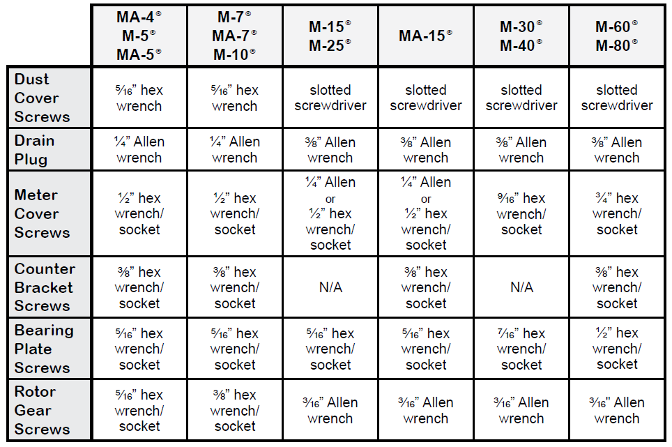
•Wrench and Socket Size Chart
Reassembling the bearing plates and rotors
Follow this procedure to reassemble the Meter:
1.Replace the non-rotor gear bearing plate to the housing with the bearing plate screws.
NOTE: The rotor gears are on the rear bearing plate of MA-4®, M-5®, and MA-5® old style models, M-60® and M-80® current models. On all other models, the rotor gears are on the front bearing

2.Insert the non-tapered ends of the three rotors into the housing and onto its respective bore of the installed bearing plate.
NOTE: For MA-4®, M-5®, and MA-5® old style models, M-60® and M-80® current models, make sure that the teeth of the driving reduction gear mesh with the teeth of the driven reduction gear.
3.Place the remaining bearing plate over the three tapered rotor ends and fasten it to the housing with the bearing plate screws.

4.The rotors should have a small amount of end-play and be easy to turn. Test each rotor, one at a time. Turn the rotors to make sure that they revolve freely. Jog the rotors from end to end to check for end-play. If they do not move easily in both tests, remove the rotors and check for burrs and corrosion deposits. Clean them thoroughly and repeat steps 2, 3 and 4.
5.Each rotor has a notch, or “keyway”, to hold a rotor key. The rotor key is a small wedge of metal. Press a rotor key into the keyway of each rotor with your thumb and forefinger.

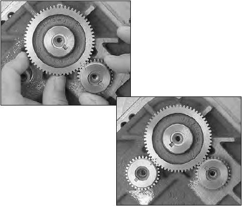
Timing the rotor gears
Before putting the meter into service, the rotors must be timed. Rotors are timed by lining up timing marks stamped onto the face of the gears. The timing mark on the blocking rotor gear is stamped on a gear tooth. The timing mark on the displacement rotor gears is stamped on a space between two gear teeth. You may need to remove the gears and reposition them several times to line up the timing marks correctly.
Torque the Gear Screw |
For step 6 in the following procedure, tighten the gear screws to the torque specification given in the Torque Chart section below. |
Follow this procedure to time the rotor gears:
1.Slide the blocking rotor gear over the tapered blocking rotor end and turn it until the timing mark is in position to line up with the timing mark on the right displacement rotor gear. Slide the right displacement rotor gear over the tapered end of the rotor so that the timing mark lines up with the blocking rotor gear timing mark.
2.Turn the blocking rotor gear (turn the right displacement rotor gear with it) until the timing mark is in position to line up with the timing mark on the left displacement rotor gear. Slide the left displacement rotor gear over the tapered end of the rotor so that the timing mark lines up with the blocking rotor gear timing mark.
3.Position the spare displacement rotor gear between the left displacement rotor gear and the blocking rotor gear to prevent the gears from moving. Attach the right displacement gear washer and screw using the rotor gear wrench.
4.Keep the spare displacement rotor gear positioned by the left displacement rotor gear. Attach the left displacement gear washer and screw using the rotor gear wrench.
5.Position the spare displacement rotor gear between the right displacement rotor gear and the blocking rotor gear.
6.Attach the blocking rotor gear with the packing gland driver and screw using the rotor gear wrench.

7.Rotate the gears to make sure that the rotors turn freely. Burrs, foreign material, or marred surfaces can restrict the rotor movements. If the rotors do not turn freely, remove the gears and rotors and deburr and clean the surfaces again.
Completing the Meter Reassembly
Tightening Front and Rear Covers |
For step 2 in the following procedure, Liquid Controls recommends tightening the front and rear cover screws in a criss-cross or “star” pattern with a minimum of two passes. First pass should be at half-torque. Final pass(es) should be at full torque. This method will ensure uniform seal compression on cover O-ring or gasket. See the Torque Pattern M-7® Front and Rear Cover section below in this topic. |
Refer to the figure below and follow this procedure to complete reassembly of the Meter:
1.Push the O-ring (1) into the groove (2) on the front of the meter housing.
NOTE: M-60® and M-80® models use a flat gasket.
2.Fasten the front cover (3) to the housing with the cover screws (4) using the cover socket or open end/box end wrench.
3.Screw the front drain plug (6) into the front drain plug hole (7) using the drain plug allen wrench.
4.Push the O-ring (8) into the groove (9) on the rear of the meter housing.
NOTE: M-60® and M-80® models use a flat gasket.
5.Fasten the rear cover (10) with the cover screws (11) using the cover socket or open end/box end wrench.
6.Screw the rear drain plug (not shown) into the rear drain plug hole using the drain plug allen wrench.
7.Screw the counter bracket (12) onto the front cover using the counter bracket screws.
8.Insert the packing gland assembly (13) through the counter bracket and into the cover plate. Make sure the forks of the packing gland drive are in the slots of the packing gland driver attached to the blocking rotor gear.
9.Screw the packing gland retaining plate onto the counter bracket using the two retaining plate screws. See Servicing the Packing Gland in Servicing the Drive Components for more information.
10.Return the adjuster drive gear (14), the adjuster drive shaft (15), and the drive shaft bushing (16) to the inside of the counter bracket. Make sure the drive gear is in its original position. See Reversing the Meter Registration for more information.
11.Screw the retaining spring (17) over the drive shaft bushing and slide the retaining ring back into the slot on the drive shaft.
12.Screw the standard adjuster (18) onto the adjuster mounting plate (19).
13.Insert the standard adjuster and adjuster mounting plate through the top of the counter bracket and onto the adjuster drive shaft. Screw the mounting plate onto the counter bracket.
14.Screw the dust cover onto the counter bracket using the dust cover screws.

Torque Chart

Torque Pattern M-7® Front and Rear Cover

Wrench and Socket Size Chart
ROTOR GEAR SCREWS |
It's important to apply these techniques when repairing meters in the field:
1.Prior to installation, apply a small amount of Locquic Primer N764 to each screw. 2.Apply a light coat of Loctite 242 in three even strokes to each screw. The Loctite and Locquic primer are not to be applied to the female connection in the rotor. |