This topic explains how to disassemble the Meter, including how to:
•Remove non-corroded rotor gears
•Remove corroded rotor gears
•Remove the bearing plates and rotors
Follow this procedure to begin disassembling the Meter:
1.Remove the counter bracket screws with a box wrench or socket driver. The counter bracket can be removed with or without removing the adjuster assembly.
2.Turn the meter on either the inlet or outlet side. Let it stand to allow the product to drain from the meter chamber.
3.Locate the drain plugs on the front and rear covers. Remove the drain plugs using an allen wrench. Let the meter stand to allow product to drain from the front and rear covers.

4.Use a socket wrench or box end wrench to remove the screws securing the front cover. Remove the screws that hold the rear cover. The number of screws will vary depending on meter size.
5.Remove the front and rear covers.
NOTE: MA-4®, M-5®, and MA-5® old style models, M-60® and M-80® current models have a driven reduction gear attached with a shoulder bolt to the center of the front.
6.Carefully remove the O-rings / flat gaskets from front and rear of the housing.
O-rings & Flat Gasket Replacement: Undamaged Buna or Viton O-rings may be reused. Flat gaskets and PTFE O-rings should always be replaced and never reused.

7.Use the rotor gear wrench (or a socket driver) to remove the right displacement rotor gear screw and washer. Hold a spare displacement rotor gear between the right displacement rotor gear and the blocking rotor gear to keep them from turning (if unavailable, use a shop rag between gear teeth).
NOTE: MA-4®, M-5®, and MA-5® old style models, M-60® and M-80® current models have rotor gears on the meter back. All other models have rotor gears are on the front.

8.Use the rotor gear wrench (or a socket driver) to remove the blocking rotor screw and the packing gland driver held by the screw. Hold the spare gear between the left displacement rotor gear and blocking rotor gear.
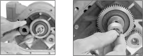
9.Use the rotor gear wrench (or a socket driver) to remove the left displacement rotor gear screw and washer. Hold the spare gear between the right displacement rotor gear and the blocking rotor gear.

Removing Non-Corroded Rotor Gears
Follow this procedure to remove non-corroded gears:
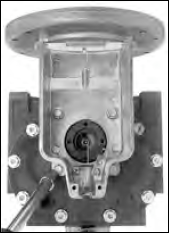
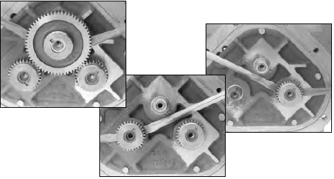
1.Insert two standard screwdrivers behind the blocking rotor gear: Gently pry the gear off its rotor tapered end. If the gears show signs of corrosion, or do not pry off easily, see To remove corroded rotor gears: below.
2.Use the same method to remove the left rotor gear and the right rotor gear. If the gears show signs of corrosion or do not pry off easily, see the section below on how to remove corroded rotor gears.
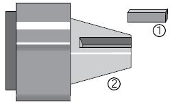
3.As each gear comes off the rotor remove the key (1) from the rotor keyway (2). Save the key to use when reassembling the meter.
4.Use the bearing plate wrench (or a socket driver) to remove the screws that hold the front bearing plate to the meter housing.
5.Remove the screws that hold the rear bearing plate to the housing.
Removing Corroded Rotor Gears
Follow this procedure to remove corroded gears:
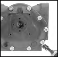
1.On the back of the meter housing, remove the screws that hold the rear bearing plate to the housing using the bearing plate wrench (or a socket driver). The number of screws will vary depending on meter size.

2.Replace all three rotor gear screws, without washers. Screw them halfway onto each of the rotor ends.
3.With a plastic or non-metallic mallet, tap on the heads of the screws on the rotor ends lightly and equally, slowly driving the rotors off of the rotor gears. As you tap on the screws, the rear bearing plate and the rotor assembly will separate from the housing.
NOTE: For carbon insert bearing plates, remove the rear plate first and then each rotor as it is hand supported.

4.Use the bearing plate wrench (or a socket driver) to remove the screws that hold the front bearing plate to the meter housing. The number of screws will vary depending on meter size.

Remove the Bearing plates and Rotors
Avoid scratching, defacing, or marring any surfaces |
Be careful not to mar or alter the shape of any of the parts. Changing the shape of the parts may interfere with their operation. |
Follow this procedure to remove the bearing plates and rotors:
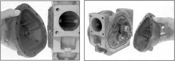
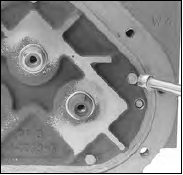
1.Insert a screwdriver into each of the two notches near the dowel pins. Gently pry the front bearing plate off the dowel pins.
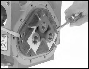
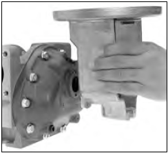
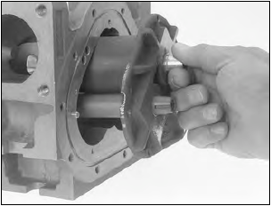
2.Grab the end of the blocking rotor extending out from the front bearing plate, and pull the front bearing plate and rotor assembly straight out from the housing.
NOTE: For MA-4®, M-5®, and MA-5® old style models, M-60® and M-80® current models, pull rotor assembly with the rear bearing plate from the housing. This will also remove the drive reduction gear which is attached to the blocking rotor.
3.Remove the remaining bearing plate. Insert a screwdriver into each of the two notches near the dowel pins. Gently pry the front bearing plate off the dowel pins.
NOTE: MA-4®, M-5®, and MA-5® old style models, M-60® and M-80® current models have a driven reduction gear attached by a shoulder bolt in the center of the front.
4.Inspect and clean all critical surfaces: gear teeth, rotors, and internal housing faces.
5.Remove any crystalline formations using fine emery cloth or a fine wire brush.
6.Remove nicks and burrs on metal parts with a stone.
7.Remove all grit and other foreign particles.
8.Replace all parts that appear worn or damaged.