This section includes the following topics:
•Removing the Dust Cover
•Servicing the Adjuster and Adjuster Drive Assembly
•Servicing the Packing Gland
•Packing Gland Retaining Plate
Before continuing to the procedures below, it's important to heed the following cautions and warnings.
 |
RELIEVING INTERNAL PRESSUREAll internal pressure must be relieved to zero pressure before disassembly or inspection of the strainer, vapor eliminator, any valves in the system, the packing gland, and the front or rear covers. Serious injury or death from fire or explosion could result in performing maintenance on an improperly depressurized and evacuated system. Strictly follow this procedure Relieving Internal Pressure Procedure for LPG and NH3 Meters: 1.Close the belly valve of the supply tank. 2.Close the valve on the vapor return line. 3.Close the manual valve in the supply line on the inlet side of the meter. If no manual valve exists on the inlet side, consult the truck manufacturer for procedures to depressurize the system. 4.Slowly open the valve/nozzle at the end of the supply line. 5.After product has bled off, close the valve/nozzle at the end of the supply line. 6.Slowly crack the fitting on top of the differential valve to relieve product pressure in the system. Product will drain from the meter system. 7.As product is bleeding from the differential valve, slowly reopen and close the valve/nozzle on the discharge line. Repeat this step until the product stops draining from the differential valve and discharge line valve/nozzle. 8.Leave the discharge line valve/nozzle open while working on the system. |
Removing the Dust Cover
NOTE: Prior to removing the dust cover, see both the warnings above and the Safety Procedures topic.
Follow this procedure to remove the dust cover:
1.Cut the dust cover seal wire with side cutters.
2.Remove the dust cover screws with a 5/16" wrench or slotted screwdriver.
3.Remove the dust cover.
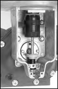
Servicing the Adjuster and Adjuster Drive Assembly
Remember to Reassemble to the Original Position |
Make sure to return the adjuster drive gear to its original position when reinstalling or the meter counter will run backwards. The gear will be set either below or above the packing gland pinion. |
Follow this procedure to remove the adjuster and adjuster drive assembly:
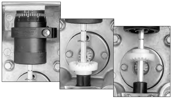
1.Record the adjuster micrometer setting and note the adjuster drive gear position.
2.Use a standard screwdriver to loosen (or remove) the two retaining spring screws.
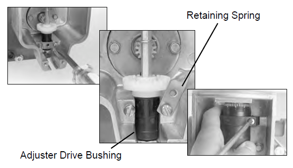
3.Swing the retaining spring off the adjuster drive bushing.
4.Loosen the adjuster mounting clamp screw with a Phillips head screwdriver.
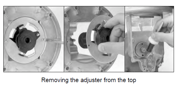
5.Remove the adjuster from the top of the meter by:
- Removing screws that secure adjuster mounting plate to counter adapter.
- Lifting adjuster mounting bracket with the adjuster out of the counter adapter.
- Removing the adjuster drive assembly from the housing.
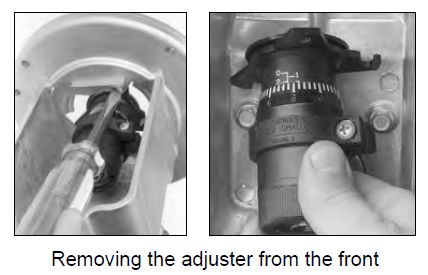
6.Remove the adjuster from the front of the meter by:
- Remove the adjuster drive assembly from the adapter and from the housing.
- Remove the slotted head screw that secures the adjuster to the mounting plate.
- Slowly pull the adjuster out through the front of the meter, rotating it from left to right to clear the adjuster mounting plate.
- Pull the adjuster down to remove from the meter.
Servicing the Packing Gland
After prolonged use, the packing gland may show leakage from the metering chamber. Leakage is a sign of wear, resulting from the type of product being metered, the operating temperature, and other system conditions. If the packing gland shows leakage, it should be replaced or repaired. The packing gland can be serviced in the field.
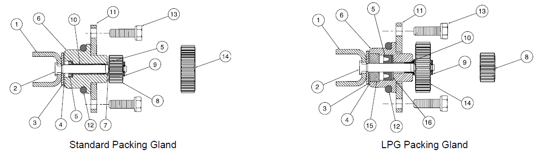
Packing Gland Components (refer to the figures below)
1.Driver 2.Shaft 3.Stainless steel thrust washer 4.Rulon thrust washer 5.Buna/Viton/PTFE “U” Cup 6.Aluminum/stainless housing 7.Washer - Nylon 8.Output gear 2:1 |
9. Retaining ring 10. Bushing 11. Retaining plate 12. Buna/Viton/PTFE O-ring 13. Two retaining plate screws 14. Output gear 1:1 15. Carbon Guide Bearing 16. Washer - Stainless Steel |
Remove the Packing Gland
Follow this procedure to remove the packing gland:
1.Remove the two screws on the packing gland retaining plate with a 5/16” socket and ratchet drive extension or 5/16” nut driver.
2.Pull out the packing gland.
3.Pry off the retaining ring with a standard screwdriver.
4.Pull the driver out from the assembly.
Packing Gland Retaining Plate
The retaining plate for the packing gland has four holes: two drilled 1½" holes on center and two drilled 1⅝" holes on center. If your meter has a counter adapter dust cover (item 0366) shaped like the illustration on the left, mount the retaining plate using the two 1⅝" holes. If your meter does not have the counter adapter dust cover like the illustration on the left, mount the retaining plate using the two 1½" holes.
|
RELIEVING INTERNAL PRESSUREAll internal pressure must be relieved to zero pressure before disassembly or inspection of the strainer, vapor eliminator, any valves in the system, the packing gland, and the front or rear covers. See the warnings about relieving internal pressure at the beginning of this topic. |