The Register is available in two separate mounting options: meter mount and panel mount.
The Register can be mounted directly onto a flow meter; however, it may also be mounted away from the meter in a more ergonomic or advantageous position, on a control panel or control pedestal. If the meter is equipped with an external POD pulser, the Register can be mounted up to 1000 feet (304 meters) away from the meter (actual distance depends on pulser specifications and wire type).
•The meter mount design consists of an enclosure base with a round mounting surface that mates perfectly with standard LC register adapter bracket or industry standard register mount and can be mounted in 45° increments.
•The panel mount design consists of an enclosure base with mounting tabs to allow the register to be conveniently mounted on a flat panel from the front or rear of the panel for a very clean and wire-free installation from the operator's point of view.
Meter Mount Housing 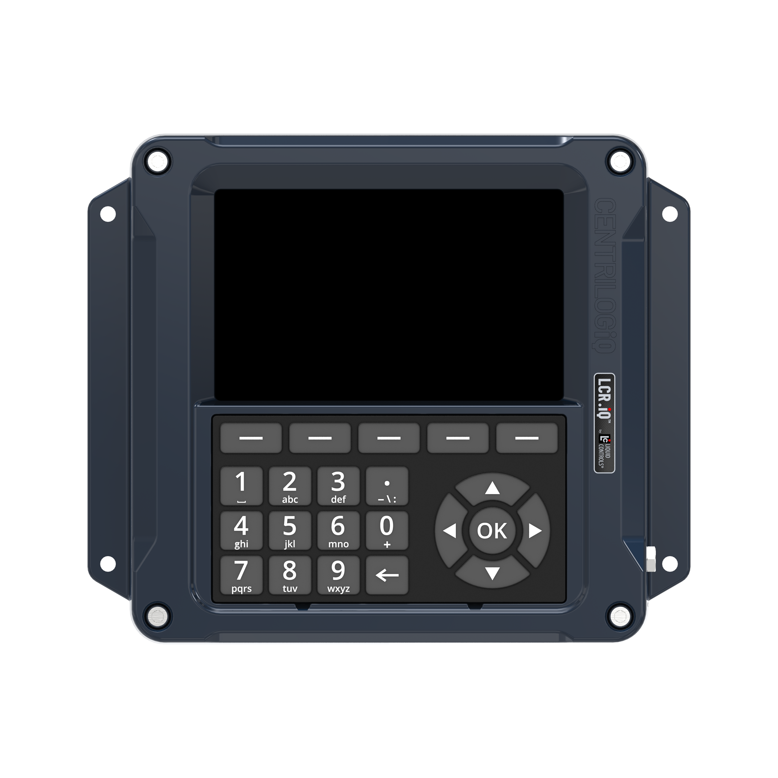 |
Panel Mount Housing 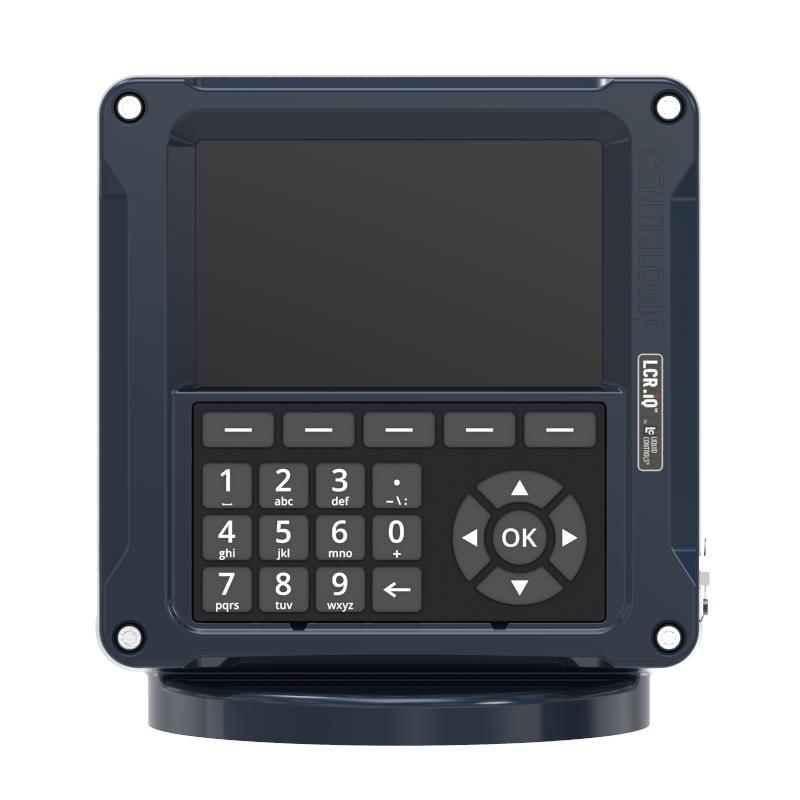 |
Adapters are available for other PD meters such as Neptune (PNs 81364, 82641, 82642), FMC Smith (PN 81370), and Brooks/Brodie (PN 81800) meters. Each kit includes installation instructions.
Tips for mounting a Register |
•Leave the cover assembly fastened to the base to protect the internal components. •Ensure that the vertical drive shaft from the meter is attached to the pulser drive shafts. •Before securing the Register to the meter or mounting bracket, ensure that the counter is visible and the keypad and calibration screw can be easily operated. |
|
Relieving Internal PressureAll internal pressure must be relieved to zero pressure before disassembly or inspection of the strainer, vapor eliminator, any valves in the system, the packing gland, and the front or rear covers. |
WARNING: Serious injury or death from fire or explosion could result in performing maintenance on an improperly depressurized and evacuated system. |
Relieving Internal Pressure Procedure for LPG and NH3 Meters Follow these steps:
1.Close the belly valve of the supply tank. 2.Close the valve on the vapor return line. 3.Close the manual valve in the supply line on the inlet side of the meter. If no manual valve exists on the inlet side, consult the truck manufacturer for procedures to depressurize the system. 4.Slowly open the valve/nozzle at the end of the supply line. 5.After product has bled off, close the valve/nozzle at the end of the supply line. 6.Slowly crack the fitting on top of the differential valve to relieve product pressure in the system. Product will drain from the meter system. 7.As product is bleeding from the differential valve, slowly reopen and close the valve/nozzle on the discharge line. Repeat this step until the product stops draining from the differential valve and discharge line valve/nozzle. 8.Leave the discharge line valve/nozzle open while working on the system.
|
|
Always apply anti-seize to all bolt threads to ensure easy removal at a later date. |