Meter menu options allow the user to set up information specific to the meter that is connected to the Register. It will be identified by the I/O Board #, UID, and Name fields.
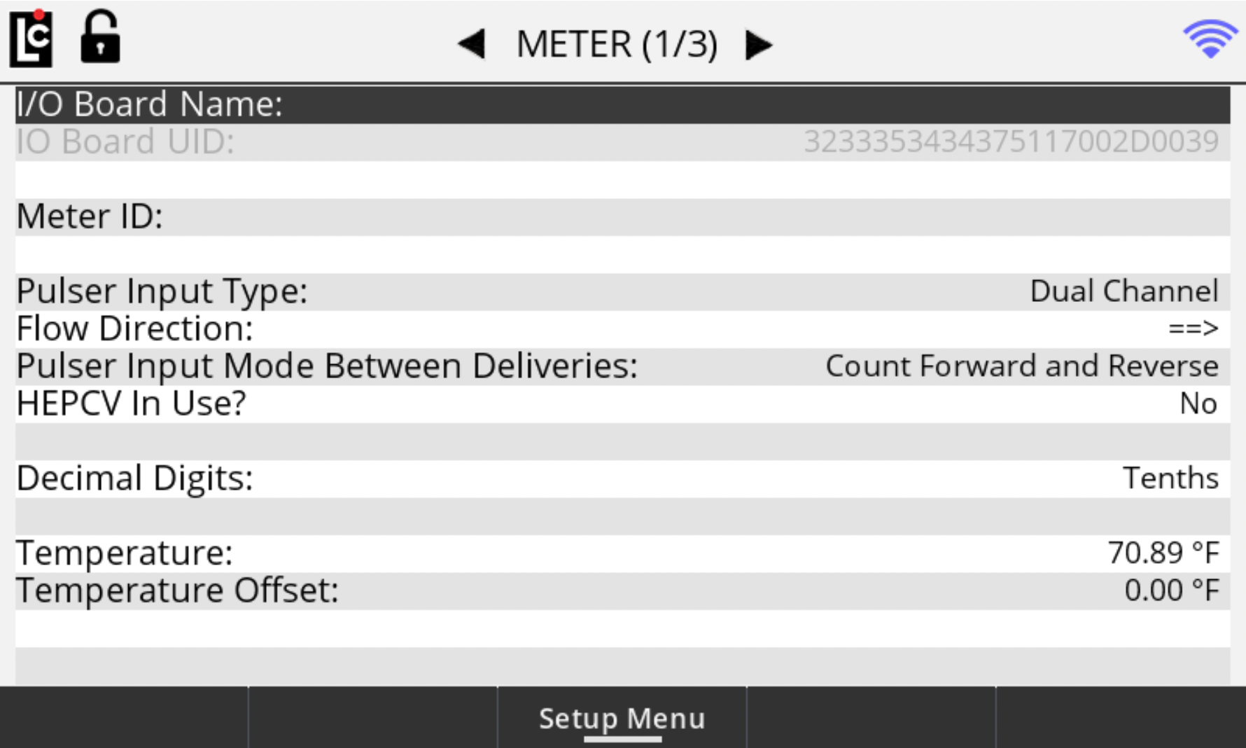
Meter (1/3)
IOBoard# – A numeric-only text field for identifying an I/O board that is connected to the Register. Settings for the each I/O board can be made when the selected I/O board appears in this field. The main I/O board in the Register is always I/O board 0. (Maximum setting is currently 0)
I/O Board UID – This read-only fields displays the serial number of the I/O board# that is currently selected.
I/O Board Name – A text field for identifying the currently selected I/O board in the I/O board # field. The name will also appear in other screens to clearly identify the selected board. (Maximum - 16 alphanumeric characters)
Meter ID – A text field for identifying a meter that is connected to the Register, Typically, the serial number of the meter is entered here. The value of this field is also printed on the Register calibration ticket. (Maximum - 10 alphanumeric characters)
Pulser Input Type – A list box for selecting the type of pulse input signal that will be connected to the selected I/O board.
Options:
•Dual Channel - 2 channel quadrature pulser signal such as the Register internal pulser or a POD pulser.
•All Single Channel - Single channel square wave signal
•Triple Channel - 3 channel pulser square wave signal
•None - No pulser is connected to the Register
Flow Direction – A list box field for inverting the direction of flow within the Register. If the register is counting in the reverse direction when first installed, inverting the flow direction will cause the register to count in the opposite direction.
Options:
•==>
•<==
Pulser Input Mode Between Deliveries – A list box field for specifying how the Register will respond to any registered pulse signal when the register is not in an active delivery.
Options:
•Count Forward and Reverse - A registered pulse signal–either forward or reverse–will directly affect the accumulative totalizer readings. It will also display the volume on the idle delivery screen.
•Forward Count Only - A registered pulse signal, in the forward direction only, will directly affect the accumulative totalizer readings. It will also display the volume on the idle delivery screen.
•Ignore - Any pulse signal that is detected when a delivery is not active will be ignored by the Register.
•Reverse Count Only - A registered pulse signal, in the reverse direction only, will directly affect the accumulative totalizer readings. It will also display the volume on the idle delivery screen.
HEPCV In Use? – A list box for enabling or disabling the Hose End Press Control Valve. This feature is to be enabled only when using a hose end press control valve in an aviation fueling system. This feature is designed to reduce back pressure and flow surges in the system.
Options:
•Yes – Enables HEPCV
•No – Disables HEPCV
Decimal Digits – A list box field that sets the decimal place for the displayed volume and also the shift and accumulative totalizers.
Options:
•Whole - Sets the decimal place to the whole units position (xxxxxx)
•Tenths - Sets the decimal place to the tenth unit position (xxxxx.x)
•Hundredths - Sets the decimal place to the hundredths position (xxxx.xx)
•Thousandths – Sets the decimal place to the thousandths position (xxx.xxx)
Temperature – This numeric-only text field displays the current temperature sensed by the Register temperature probe when installed. Use this field to set a temperature offset, if the value is within the allowed range of the temperature offset field below. If no probe is installed, this value will read --.- .
Temperature Offset – A numeric-only text field for specifying an offset to the value of the current temperature reading. A value of +/- .54 degrees F or +/- .3 degrees C is allowed by Weights and Measures. When an offset is entered and within the acceptable range, the current temperature will automatically be adjusted by the amount of this value. (Floating point from -.30 to +.30°C or -.54 to +54°F)
Meter (2/3)
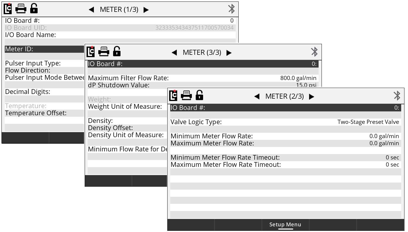
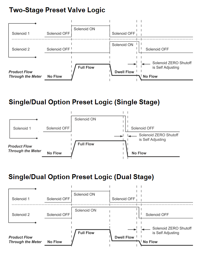
Valve Logic Type – A list box field that is used to select the logic to be used when connecting a solenoid valve to the Register.
Options:
•Two-Stage Preset Valve - This logic is to be used with standard 2 stage preset valves. With this logic, only S1 will open for full flow when a delivery starts. S2 will only open for dwell (slow) flow. This logic is the same as in the LCR-II and LCR 600 registers.
•Single/Dual Option Preset Valve - This logic can be used when using single or dual stage preset valves. With this logic both S1 and S2 will energize at the start of a delivery. If an S1 close time is set, S1 will drop out when the S1 close is reached and S2 will remain open until the final closure amount reached.
Minimum Meter Flow Rate – A numeric text field that can be used to set a minimum flow rate value for the Register. If the delivery flow rate drops below this value for a duration greater than the Minimum Flow Rate Timeout value, the delivery will be paused by the register and an error message generated to inform the user that the Minimum Flow Rate was detected. (Maximum - 6 numeric characters)
Maximum Meter Flow Rate – A numeric text field that can be used to set a maximum flow rate value for the Register. If the delivery flow rate rises above this value for a duration greater than the Maximum Flow Rate Timeout value, the delivery will be paused by the register and an error message generated to inform the user that the Maximum Flow Rate was exceeded. (Maximum - 6 numeric characters)
Minimum Meter Flow Rate Timeout – A numeric text field that can be used to set the timeout duration for the minimum flow rate. This is the amount of time, in seconds, that the minimum flow rate can drop below the set Minimum Flow Rate valve before the delivery pauses. (Maximum setting - 15 sec)
Maximum Meter Flow Rate Timeout – A numeric text field that can be used to set the timeout duration for the maximum flow rate. This is the amount of time, in seconds, the maximum flow rate can rise above the set Maximum Flow Rate valve before the delivery pauses. (Maximum setting - 15 sec)
Meter (3/3)
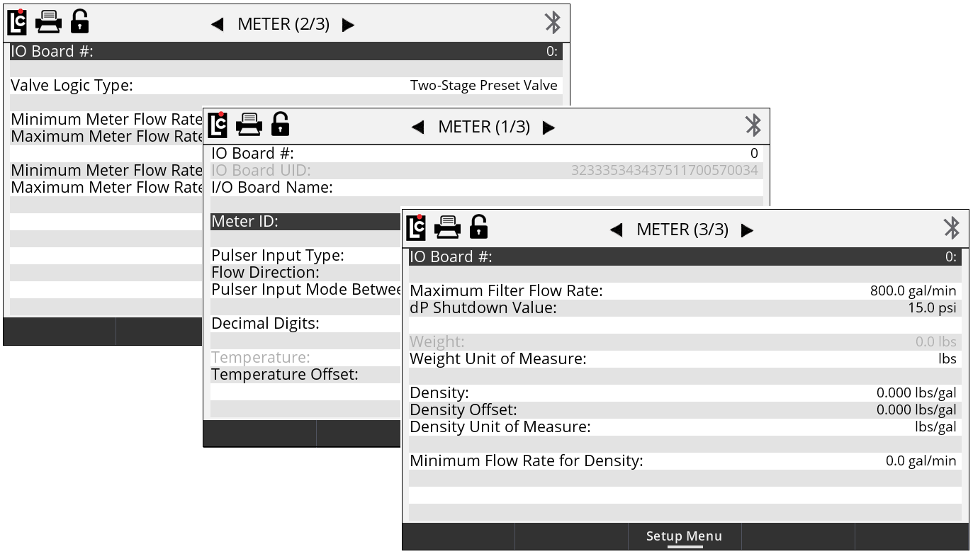
Maximum Filter Flow Rate – A numeric only text field that is used along with a Liquid Controls Differential Pressure Transducer (dP) to calculate corrected differential pressure based on the maximum rated flow rate of the filter vessel. This field should be set to the maximum flow rate rated on the filter housing. This option only applies when a Liquid Controls dP transducer is connected to the Register. (Maximum setting - 9999.9)
dP Shutdown Value – A numeric only text field that should be set to the maximum differential pressure allowed (JIG Standard 15 PSI) when using the Liquid Controls Differential Pressure Transducer. This option only applies when a Liquid Controls dP transducer is connected to the Register. The maximum setting is 60 psi (The Current JIG standard is 15 PSI)
Weight – A read only field that displays a weight value when using Liquid Controls Automatic Density Sensor or entering a manual density value into the Register.
Weight Unit of Measure – A list box field that is used to select the unit of measure for weight when using this feature.
Options:
•kgs - Kilograms
•lbs - Pounds
Density – A numeric only text box that can either have a density value manually entered or automatically generated using the Liquid Controls Automatic Density Sensor. The maximum setting is 999.999
Density Offset – A numeric only text box that can be used to add an offset to the value measured by the Automatic Density Sensor when installed. This setting has a fixed adjustment of +/- 0.8 units.
Density Unit of Measure – A list box field that is used to select the unit of measure for density when using this feature.
Options:
•kg/L - Kilograms per Litre
•kg/bbl - Kilograms per Barrel
•kg/gal - Kilograms per Gallon
•kg/m3 - Kilograms per Meter Cubed
•lb/L - Pounds per Litre
•lb/bbl - Pounds per Barrel
•lb/gal - Pounds per Gallon
•lb/m3 - Pounds per Meter Cubed
Minimum Flow Rate Density – A numeric text box that can be used to set a minimum acceptable flow rate value when calculating density. This value will vary according to the acceptable minimum flow rate of the meter and should never be set below the minimum rated volumetric flow rated on the meter. (Maximum setting - 999999 Units)