Calibration menu options allow the user to set up and calibrate up to 16 specific products for delivery on the Register. There are four Calibration Settings screens.
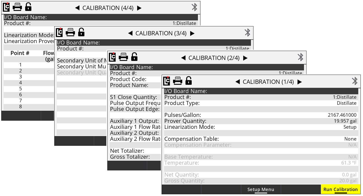
Calibration (1/4)
IO Board Name – A text field that is used to identify the currently selected I/O board in the I/O board # field. The name will display on other screens as well to clearly identify the selected board. (Maximum - 16 Alphanumeric characters)
Product # – A list box containing the 16 products that are available for setup and calibration with the Register.
Options:
•Products 1-16 are available for setup. Only setup and calibrate products that are to be used by the Register.
Product Type – A list box for selecting the product (classification) type. The product type will print on all calibration and diagnostic ticket,s and it will designate the Product Type for each Product Number. The product type will also appear on all delivery tickets to assist in identifying the delivered product.
Options:
•Ammonia
•Aviation
•Distillate
•Gasoline
•LPG
•Lube Oil
•Methanol
•Blank
Pulses/Unit (Gallon, Liter…) – A numeric-only text field for specifying the number of pulses that equal the whole-unit of measure for the product being setup on the Register. This number is most important, since it directly affects the calibration of the meter. (Maximum setting - 20000.000000 units)
NOTE: A chart of starting reference calibration factors can be found in an appendix to this manual. Refer to this chart for assistance in selecting a starting Pulses/Unit number. |
Prover Quantity – A numeric-only text field for calibrating the product currently being set up. This field is used during calibration to enter the known prover quantity of a volumetric proving device or master meter. After a calibration run, entering a value into this field will automatically adjust the Pulse/Unit field by the percent error that is calculated. Learn more in Single-point Calibration.
Linearization Mode – A list box for applying multi-point calibration, when such calibration is in use. Setting this field to Applied will activate multi-point calibration, if all parameters have been met for using multi-point calibration. For instructions on how to perform multi-point calibration, see Multi-point Calibration.
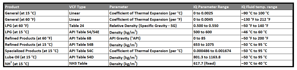
Compensation Table – A list box for selecting and using temperature compensation on a product that is being set up. See the Compensation Types and Parameter chart below for details of each table.
Options:
•None - Select None if no temperature compensation is to be used
•Table 24 - Select this table for LPG (USA)
•Table 54/54E - Select this table for LPG (Canada and Europe)
•Table 54B - Select this table for Refined Petroleum (Canada and Europe)
•Table 54C - Select this table for Specialized Products (Canada and Europe)
•Table 54D - Select this table for Lube Oil (Canada and Europe)
•Table 6B - Select this table for Refined Petroleum (USA)
•Linear C - Select this table for a general Linear table when measuring Celsius
•Linear F - Select this table for a general Linear table when measuring Fahrenheit
•NH3 - Select this table for measuring Ammonia (Canada)
Compensation Parameter – A numeric-only field whose parameter is dependent on the Register Parameter Range listed in the compensation table that was chosen in the list box.
Base Temperature – A numeric-only field that sets the base temperature according to the Register compensation table that was chosen in the list box.
Temperature – A read-only text field that displays the current temperature of the Register–if a temperature probe is connected.
Net Quantity – A read-only text field that displays the current net volume of the last delivery made with the Register. If temperature compensation is not active, this field will not increment.
Gross Quantity – A read-only text field that displays the current gross volume of the last delivery made with the Register.
Calibration (2/4)

Product # – A list box that list the 16 products that are available for setting up and calibrating the Register.
Options:
•Products 1-16 are available for setup. Only setup and calibrate products that are to be used by the Register.
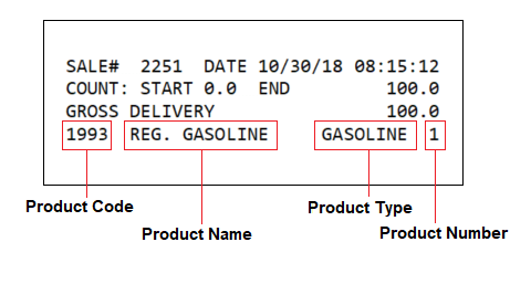
Product Code – A text field for identifying the selected product with a code.The product code will appear on all ticket formats to identify the product that was delivered, as shown above. (Maximum - 5 alphanumeric characters)
Product Name – A text field for identifying the selected product with a specific name. The product name will appear on all ticket formats to identify the product that was delivered as shown above. (Maximum - 18 alphanumeric characters)
S1 Close Quantity – A numeric text field that is used with 2 stage preset valves. This value sets the number based on the unit of measure that will transition a 2 stage valve from high flow to low flow–for an accurate preset stop. For more information on setting up the S1 closure, see Setting the S1 Close time. (Maximum - 5 alphanumeric characters)
Pulse Output Frequency – A numeric text field that determines the number of output pulses per unit of measure when using the calibrated pulse output feature of the Register. Setting this field to 1 will result in a 1:1 pulse output to the unit of measure. The maximum value that can be set for this field will vary depending on the decimal setting for the unit of measure and the K-Factor (Pulses/Unit) of the product.
•Hundredths - Max 1% of the K-Factor
•Tenths - Max 10% of the K-Factor
•Whole - Max 50% of the K-Factor
Pulse Output Edge – A list box that determines the signal direction of the calibrated pulse output. Toggling this setting can help align the pulse output of the Register with a remote counter or injection system by inverting the output square wave resulting in an opposite adjustment in the signal.
Options:
•Rising - The pulse output square wave from the Register
•Falling - The inverted pulse output square wave from the Register
Auxiliary 1 Output – A list box that determines how any digital output that is set to AUX 1 will operate based on the selected product on the Register. There are several features in the Register that can be performed based on the Aux settings to control external components such as pumps, injectors, PTO, throttle, alarms, reset pulse, etc.
Options:
•Off - Any output set to AUX 1 Calibration Mode Settings will always be off (Not active)
•On - Any output set to AUX 1 Calibration Mode Settings will always be on (Active and Sinking to ground)
•On - During Active Delivery - Any output set to AUX 1 Calibration Mode Settings will turn on (Sink to ground) when a delivery is started and will turn off when End is pressed and the delivery is complete.
•On - During Run State - Any output set to AUX 1 Calibration Mode Settings will turn on (Sink to ground) when a delivery is active and not paused. The output will be on when a delivery starts. However, if the delivery is paused by issuing a stop command, the output will turn off until the resume command is given. If the end of delivery command is given, the output will remain off and the delivery will end.
•On - Flow Rate Monitor - Any output set to AUX 1 Calibration Mode Settings will be on when a delivery is active, however it will deactivate if the flow rate meets or exceeds 40 units/time. If the flow rate does not meet or exceed 40 units/time, the output will remain on.
•On - Reverse Flow - Any output set to AUX 1 Calibration Mode Settings will be off when a delivery starts, and will only turn on when the register detect flow in the negative or reverse direction.
•Reset Pulse/Delivery Start - Any output set to AUX 1 Calibration Mode Settings will output a short pulse at the start of a delivery that is used with 3rd party remote counters that require a reset pulse to reset to 0.0.
•Toggle Flow Rate - Any output set to AUX 1 Calibration Mode Settings will turn on once the flow rate of the Register exceeds the set flow rate point in the Auxiliary 1 Flow RateToggle field below.
•Calibrated Scaled Pulse Output - Any output set to AUX 1 Calibration Mode Settings will output a calibrated pulse output–that is scaled according to the Pulse Output Frequency setting in the calibration mode.
Auxiliary 1 Flow Rate Toggle – A numeric text field that can be used to program a flow rate set point when the Aux 1 is set to Toggle flow rate. Auxiliary 1 remains activated above the set flow rate value and deactivates when the flow rate falls below the value.
A common use for this output is an air operated valve (AOV) on the pump. When the flow rate value is attained, the AOV is activated and switches the pump from low-bypass pressure mode to full-flow fuel mode (high bypass pressure). When the flow rate falls below the set value, the AOV deactivates and the pump returns to low flow. Another possible use for this output is the engine throttle—to increase and decrease the RPM of the pump shaft. In applications such as these, the flow rate value in this field should be below the low flow rate with a fully open nozzle or the output will never turn on. Another application of this field is to set the value as a maximum flow rate at which a valve should be closed. On fuel delivery trucks, flow valves often activate an internal switch at approximately 18 GPM (68 LPM). The value of this field is unique to each product.
Auxiliary 2 Output – A list box that determines how any digital output that is set to AUX 2 will operate based on the selected product on the Register. There are several features in the Register that can be performed based on the Aux settings to control external components such as pumps, injectors, PTO, Throttle, alarms, and reset pulse.
Options:
•Off - Any output set to AUX 2 Calibration Mode Settings will always be off (Not active)
•On - Any output set to AUX 2 Calibration Mode Settings will always be on (Active and Sinking to ground)
•On - During Active Delivery - Any output set to AUX 2 Calibration Mode Settings will be on (Active and Sinking to ground) when a delivery is active on the Register. The output will be on when a delivery is started and will not turn off until an end of delivery command is given.
•On - During Run State - Any output set to AUX 2 Calibration Mode Settings will be on (Active and Sinking to ground) when a delivery is active and not paused. The output will be on when a delivery starts. However, if the delivery is paused by issuing a stop command, the output will turn off until the resume command is given. If the end of delivery command is given, the output will remain off and the delivery will end.
•On - Flow Rate Monitor - Any output set to AUX 2 Calibration Mode Settings will be on when a delivery is active. However, it will deactivate if the flow rate meets or exceeds 40 units/time. If the flow rate does not meet or exceed 40 units/time, the output will remain on.
•On - Reverse Flow - Any output set to AUX 2 Calibration Mode Settings will be off when a delivery is started and will only turn on when the register detects flow in the negative or reverse direction.
•Reset Pulse/Delivery Start - Any output set to AUX 2 Calibration Mode Settings will output a short pulse at the start of a delivery that is used with 3rd-party remote counters that require a reset pulse to reset to 0.0.
•Toggle Flow Rate - Any output set to AUX 2 Calibration Mode Settings will turn on once the flow rate of the Register exceeds the set flow rate point in the Auxiliary 1 Flow Rate Toggle field below.
•Calibrated Scaled Pulse Output - Any output set to AUX 2 Calibration Mode Settings will output a calibrated pulse output that is scaled according to the Pulse Output Frequency setting in the calibration mode.
Auxiliary 2 Flow Rate Toggle – A numeric text field for programming a flow rate set point, when the Aux 2 is set to Toggle flow rate. Auxiliary 2 remains activated above the set flow rate value, and deactivates when the flow rate falls below the value.
Net Totalizer – A numeric text field that shows the current accumulative net totalizer value of the current selected product on the Register. The Net Totalizer uses a non-resettable totalizer. However, it can be programmed as necessary in the Weight and Measures (Calibration) mode if reprogramming is required. (Maximum setting - 999999999 units)
Gross Totalizer – A numeric text field that shows the current accumulative gross totalizer value of the current selected product on the Register. The Gross Totalizer uses a non-resettable totalizer. However, it can be programmed as necessary in the Weight and Measures (Calibration) mode if reprogramming is required. (Maximum setting - 999999999 units)
Calibration (3/4)

Product # – A list box containing 16 products that are available for setup and calibration of the Register.
Options: Products 1-16 are available for setup. Only setup and calibrate products that are to be used by the Register.
Secondary Unit of Measure – A list box that can be set up to be the unit of measure label when printing or displaying a secondary unit of measure. See the Secondary Unit Multiplier below for setting descriptions.
Options:
•Gallon
•Barrel
•Cubic Meter
•Decalitre
•Litre
•LB (Pound)
•KG (Kilogram)
•Other

Secondary Unit Multiplier – A numeric text field for applying a multiplying factor to the primary unit of measure in order to obtain a secondary unit of measure. An example of this would be a primary unit of measure in Gallons together with a multiplier of 3.78 that is entered to create a secondary unit of measure in Litres. (Maximum setting is 9999.999)
Secondary Unit Quantity – A read-only field that will display the secondary unit of measure if programmed for use.
Calibration (4/4)

Product # – A list box containing the 16 products that are available for setting up and calibrating the Register.
NOTE:
•Products 1-16 are available for setup. Only setup and calibrate products that are to be used by the Register.
The Register provides two means of calibration, single-point [Calibration screen (1/4)] or multi-point calibration [Calibration screen (4/4)].
A “point” corresponds to a particular flow rate along the meter linearity curve. Single-point calibration adjusts one point along the linearity curve to zero percent error—typically at a flow rate representative of a normal delivery. Since meter linearity varies at different flow rates, and every meter behaves differently, the more points of calibration will generally result in more accurate fluid measurement.
Multi-point calibration zeroes the percent error at multiple flow rates (between the rated lowest flow rate and highest flow rate of the meter) in order to zero-out the linearity curve across the rated flow range.
To multi-point calibrate the meter using the Register (Calibration screen 4/4), first select point #1 and enter the lowest flow rate measured. Then, enter the % error measured at that flow rate. Repeat this for points 2 through the highest number of points measured (up to 16 points available).
Linearization Mode – A list box for applying a multi-point calibration. Setting this field to Applied will activate multi-point calibration–if all parameters are met for using multi-point calibration.
Linearization Prover Qty – A numeric only text field for performing a multi-point calibration on the currently selected product on the Register. This field is used during multi-point calibration to enter the known prover quantity of a volumetric proving device or master meter. Following a multi-point calibration run, entering a value into this field will automatically prompt the user to select a point to apply the run to, followed by a prompt to enter the flow rate that was used during the multi-point calibration run. This action will store the point and flow rate, then calculate the percent error to be applied to the selected point.
Point – A list box for selecting the calibration point for the multi-point calibration. The Register is able to perform a multi-point calibration on as many as 16 separate points.
Options:
•Linearization Points 1-16 are available for setup.
Flow Rate – A numeric text field for entering the actual flow rate at which a multi-point calibration run was made.
% Error – A numeric field that is used when the Register calculates the percent error for a multi-point calibration point. The percent error field can also be manually entered for meter systems that have a factory supplied accuracy curve.