New Installations
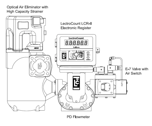
When ordering a new meter with the E-7 valve, it is supplied mounted to the outlet side of the meter. An example is the M7 meter with high capacity strainer, Optical Air Eliminator, and LectroCount LCR-II® Electronic Register shown in the figure to the right. The system piping is connected to the outlet side of the E-7 valve using the four bolts and washers provided.
The E-7 Valve solenoids are supplied pre-wired to the LectroCount Electronic Register and may be oriented with the outlet facing top, back, forward, or bottom. Air lines are connected to the Flow Control Switch via the two 1/8” NPT ports. The Flow Control Switch may be rotated in 90° increments for ideal installation orientation.
Retrofit Installations
After relieving the internal pressure from the system and draining the liquid from the meter and accessories, disconnect the outlet line from the outlet side of the meter (or the mechanical valve that your are replacing) and then remove the mechanical valve. Connect the new valve assembly to the outlet side of the positive displacement meter.
The tools necessary for installation include:
•Flat-blade screwdriver
•Phillips screwdriver
•Torx screwdriver
•7/16-inch wrench
•9/16-inch wrench
Valve Orientation
The valve has an arrow showing the direction of flow and the outlet side is clearly marked OUTLET. Position the outlet in one of four positions, depending on the application. The solenoid mounting is interchangeable from one side of the valve to the other, and it may be necessary to change it for correct positioning of the solenoids with respect to the outlet location. The best locations for the solenoid are either up “on top” of the valve or horizontally–facing back or forward. Liquid Controls does not recommend positioning the solenoids such that they face down.
Use the four bolts and washers to fasten the valve assembly to the meter. Tighten the bolts in a crossing pattern. Once this is complete, connect the outlet piping to the outlet side of the E-7 valve. The wiring instructions can be found in the Wiring section below.
Flow Control Switch Orientation
It is best to set the orientation of the flow control switch prior to filling the system with product. Remove the four fasteners holding the flow control switch to the E-7 valve.
Connecting Air Lines
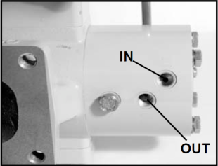
The IN and OUT air line connections on the flow control switch are 1/8-inch NPT. Use appropriate fittings and tubing for these connections. The air lines and fittings should be able to handle the air pressure provided by the system. Liquid Controls recommend maintaining the air pressure between 50 and 150 psi.
Connect the supply air to the IN port on the flow control switch. Connect the OUT air line to the component(s) that will be controlled by the flow control switch. This is typically an air-operated valve on the pump, but may also include a connection to the engine throttle control.
Orientation of the Air Switch Ports |
The ports of the air switch are shown facing the front for instruction purposes only. These ports must be oriented so that the ports face the top or bottom of the air switch. The system ships with ports facing the top, which Liquid Controls recommends. A vertical position allows any condensation from the air pump to drain. |
Adjustment
The flow control switch activation value is adjustable in the range of approximately 10-45 GPM, depending on the fueling system in use. The advantages of adjusting the switch to match the intended use include the following:
•Improve split compartment performance
•Improve system wear
•Improve efficiency
When the flow control switch ships from the factory, it is set to the mid-point of its adjustment–at approximately 30 GPM. In this position, the flow control switch will activate when the flow through the meter reaches 30 GPM. It will deactivate when the flowrate falls below 30 GPM.
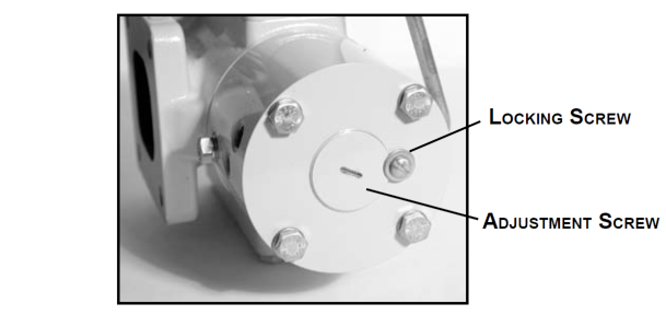
To adjust the flowrate activation setting, loosen the locking screw. The adjustment screw should have been shipped turned out ¾ turn. To set the flow control switch to a lower activation flow rate, rotate the adjustment screw clockwise. To set the flowrate at a higher activation flowrate, rotate the adjustment screw counter-clockwise. The counterclockwise adjustment from the lowest setting to the highest setting should not exceed 2 turns.
To set the activation flowrate, make small adjustments and test the system–noting the flowrate when the flow control switch engages and disengages. At the correct activation flowrate, secure the adjustment screw with the locking screw.
Prevent complete unthreading of the adjustment screw |
These adjustments can be made without removing the air supply line. However, if the adjustment screw rotates beyond two turns and completely unthreads from the housing, it will be necessary to shut off the air supply before reinstalling the adjustment screw. |

Changing Solenoid Orientation
The E-7 valve, which mounts on the outlet side of the meter, is typically oriented such that the outlet port of the valve faces the back or to the top of the meter. The valve has a symmetrical bolt pattern so it can be rotated in 90° increments. This permits the outlet side of the valve to face upward, downward, forward, or backward. To do this, remove the four bolts holding the valve in place, then rotate the valve to the desired orientation, and then refasten the bolts.
In some orientations, the solenoid manifold and the solenoid valves are upside down. This is the worst orientation for the operation of the solenoid valves. When mounting on some smaller sized meters, it may be physically impossible to rotate the valve with the solenoids pointing downward, since the solenoids would extend beyond the bottom of the meter. In either case, it is possible to switch the solenoid manifold and the valve plate.

The tools necessary for installation include:
•Flat-blade screwdriver
•Phillips screwdriver
•Torx screwdriver
•9/16-inch wrench
•7/16-inch wrench
Follow the steps below to change the orientation of the solenoid.
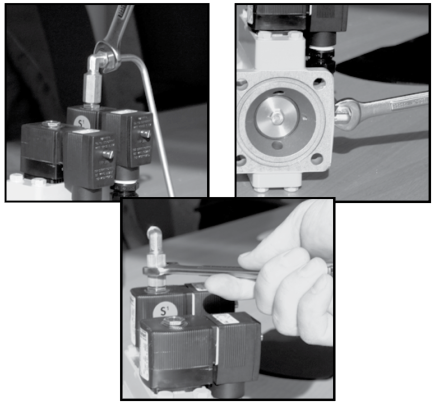
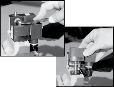
Step 1 - Remove the S1 Bypass TubingUsing an 9/16-inch wrench, loosen the two fittings on each end of the bypass tubing. Remove the tubing and set aside. Then, remove the fitting from the top of the S1 solenoid. |
|
Step 2 - Remove the S1 and S2 SolenoidsUsing an 9/16-inch wrench, remove the nuts on top of the S1 and S2 solenoids, and then lift the solenoid coils off their post. |
|
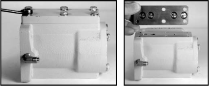
Step 3 - Remove the Solenoid ManifoldUsing a 7/16-inch wrench, remove the six screws which hold the manifold in place. Then, remove the manifold. The manifold has four O-rings which seal against the valve body. Inspect and replace these, as necessary.
|
|
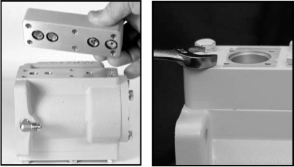
Step 4 - Remove the Valve PlateTo remove the valve plate, use a 7/16-inch wrench to remove the six screws holding it in place. Remove the valve plate from the valve body. This plate has four O-rings. These are identical to the four O-rings under the solenoid manifold. Inspect and replace these, as necessary.
|
 |
Step 5 - Remount the Valve PlateTurn the valve body over and install the valve plate on the side which originally had the solenoid manifold. Ensure that the O-ring seals are in place, and that the holes of the valve plate line up with the fastener connections of the valve body. If the center holes do not line up correctly, rotate the valve plate 180°.
|
 |
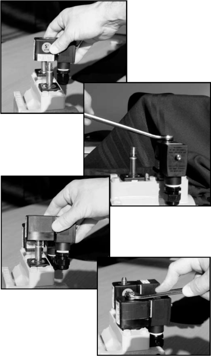
Step 6 - Remount the Solenoid ManifoldInstall the solenoid manifold on the side which originally had the valve plate. Ensure that the O-ring seals are in place, and that the holes of the solenoid manifold line up with the fastener connections of the valve body. If the center holes do not line up correctly, rotate the solenoid manifold 180°.
|
|
Step 7 - Reinstall the S1 and S2 SolenoidsPlace the solenoid coils over the posts. Position the solenoid coils facing the side of the valve most suitable for installation and repair. Replace the nuts and tighten with an 9/16-inch wrench.
NOTE: Once the bypass tubing is installed, it is not possible to rotate the S1 solenoid from one side of the valve to the other. Ensure that the solenoid is in the correct orientation before installing the bypass tubing.
|
|
Step 8 - Reinstall the Bypass TubingReplace the fitting over the S1 solenoid. Then, reconnect the bypass tubing to the solenoid fitting and the valve housing fitting. |
 |
