Liquid Controls Mechanical Air & Vapor Eliminators remove air and vapor from metering systems. Removing the air and vapor from a metering system increases the accuracy of the meter by allowing only liquid to pass through the meter for measurement.
At installation, Liquid Controls mechanical air and vapor eliminators are piped to a storage tank to provide a pathway and a receptacle where the evacuated air and vapor can be deposited. After the air (or vapor) has left the metering system, mechanical air and vapor eliminators seal off the pathway to prevent liquid from entering the storage tank. |
 |
Storage Tank |
In this manual, the term “storage tank,” refers to any type of receptacle meant to hold air or vapor expelled from the meter system by an air eliminator. Because mechanical air and vapor eliminators remove both air and vapor, depending on the application, the terms “air” and “vapor” are interchangeable throughout this guide. |
Orientation and ComponentsLiquid Controls mechanical air and vapor eliminators are typically bolted, in an upright position, onto the top of a strainer on the inlet side of the meter. Before operation, air and vapor eliminators must be piped to a storage tank and–on most meter systems– to an air-check (or differential) valve. Installation and maintenance must be done by a qualified technician. See Installation for Field Piping installation.
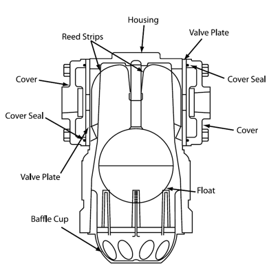
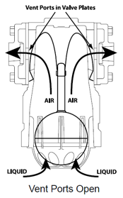
Air and Vapor EliminationLiquid Controls mechanical air and vapor eliminators eliminate air (or vapor) instantly and continuously as it enters the meter system. Because air and vapor are lighter and less dense than liquid, they are naturally pushed up above the product flow. Air and vapor eliminators are set above the product flow so that air in the system is pushed up into the the cavity inside the air eliminator housing, out the valve plate vent ports, through the piping, and into a storage tank (see "Vent Ports Open" figure).
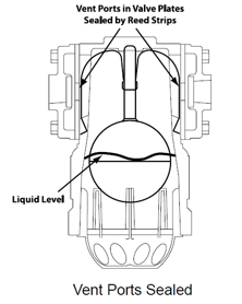
As air is evacuated from the system, the liquid level inside the air eliminator cavity is allowed to rise and push the float up. As the float moves up, it presses the reed strips against the valve plate sealing the vent ports and preventing product from passing through the piping and into the storage tank. If more air enters the system, it will rise to the top of the air eliminator cavity. The air will accumulate there and push the liquid level, and the float, lower. As the float falls, the reed strips pull away from the vent ports, and air can be vented before it enters the system. |
|
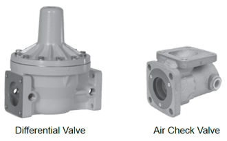
Air Check and Differential Valves
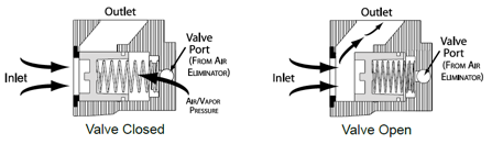
Air check and differential valves are spring loaded valves on the outlet side of the meter. Most Liquid Controls meter systems with an air eliminator also have an air check or a differential valve. Air eliminators and air-check (or differential) valves work in conjunction to stop the flow of product through the meter until the air is eliminated from the system. In order to do this, the air eliminator and the valve are piped together at installation.
Air-check (or differential) valves are normally closed, but when the pump starts and pushes product into the system, the valve spring will give way to the flow pressure. In order to keep the valve closed when air is being expelled from the air eliminator, the air from the air eliminator is routed through the piping to the back side of the valve spring. The combined force of the expelled air and the strength of the spring keep the valve closed until the air is eliminated. |
 |
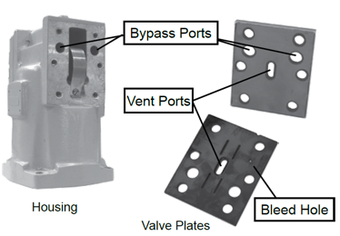
Limited Bleed Valve Plates
After the air is eliminated and the reed strips pull away from the vent ports, the air pressure on the back side of the spring is relieved and the valve opens. To avoid the system shock sustained by an abruptly opened valve, the pressure must be released slowly. In order to do this, a 1/32-inch bleed hole has been drilled into one of the valve plates so that it sits over a bypass port. The small bleed hole gradually releases the pressure on the valve spring allowing it to open it slowly. |
|
Storage Tank |
Bypass ports provide a pathway through the mechanical air eliminator housing to allow air or vapor to pass from one side of the air eliminator to the other while the valve plate vent ports are sealed. |
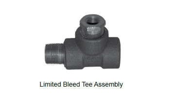
Limited Bleed Tee Assemblies
Some Liquid Controls mechanical air eliminator models are designed without bypass ports in their housings (for example, bulk plant air eliminators). For those models to retain the functions of a limited bleed valve plate, a limited bleed tee assembly can be installed in the piping. |
 |
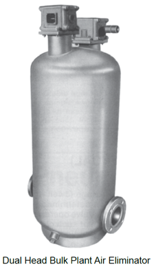
Dual-Head Bulk Plant Air Eliminators
By employing two air eliminators–a high-mount air eliminator and a low-mount air eliminator–dual-head bulk plant air eliminators save the metering system from shocks incurred by recurring small slugs of air (or vapor) and prevent large slugs of air from passing by the air eliminator and through the meter system.
Each time a standard air eliminator removes a small slug of air, it closes the downstream differential valve. When the differential valve closes at a high flow rate, meter systems can incur a significant hydraulic shock. Repeated shocks of this nature can shorten the life of the metering system.
Dual-head bulk plant air eliminators have a high-mount air eliminator that eliminate small slugs of air without stopping the product flow through the meter system to save the system from shock. Dual-head bulk plant air eliminators also have a low-mount air eliminator to remove large air slugs.
Occasionally, large slugs of air can overtake a standard air eliminator, and excess air can blow by the air eliminator and pass through the meter–which can cause inaccurate metering. With a dual-head bulk plant air eliminator and a differential valve as part of the metering system, the float in the low-mount air eliminator drops in the presence of a large slugs of air, the differential valve senses the presence of air as the pressure above and below the diaphragm, and the valve closes until the large slug of air is removed. When the float rises and the valve opens, the high-mount air eliminator removes the remaining air in the vessel.
Dual-head bulk plant air eliminators require a differential valve and they can only be mounted in fixed installations. They are ideal for applications when product is being metered into storage from a truck or transport with a pump mounted on the truck. |
|
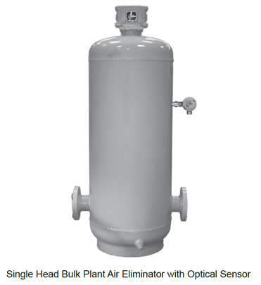
Single-Head Bulk Plant Air Eliminator with Optical Sensor
The Single-Head Bulk Plant Air Eliminator with Optical Sensor performs the same functions as the Dual-Head Bulk Plant Air Eliminator. Both air eliminators use a high mount air eliminator to siphon air without stopping the flow. But instead of a low-mount mechanical air eliminator, the Single-Head Bulk Plant Air Eliminator with Optical Sensor uses an optical sensor to identify large air slugs. When the optical sensor identifies a large air slug, it instantly signals an electronic preset or register (Toptech MultiLoad presets or Liquid Controls LectroCount registers). The electronic device closes a downstream control valve–which stops the product flow–and the air slug is quickly vented.
The optical sensor provides several advantages over its mechanical counterpart. The response time of the optical sensor is much faster than pneumatic-based mechanical air eliminators. The optical sensor has no moving parts or piping requirements, which can simplify installation and maintenance. |
|