 |
RELIEVING INTERNAL PRESSUREAll internal pressure must be relieved to zero pressure before disassembly or inspection of the strainer, vapor eliminator, any valves in the system, the packing gland, and the front or rear covers. Serious injury or death from fire or explosion could result in performing maintenance on an improperly depressurized and evacuated system. Strictly follow this procedure Relieving Internal Pressure Procedure for LPG and NH3 Meters: 1.Close the belly valve of the supply tank. 2.Close the valve on the vapor return line. 3.Close the manual valve in the supply line on the inlet side of the meter. If no manual valve exists on the inlet side, consult the truck manufacturer for procedures to depressurize the system. 4.Slowly open the valve/nozzle at the end of the supply line. 5.After product has bled off, close the valve/nozzle at the end of the supply line. 6.Slowly crack the fitting on top of the differential valve to relieve product pressure in the system. Product will drain from the meter system. 7.As product is bleeding from the differential valve, slowly reopen and close the valve/nozzle on the discharge line. Repeat this step until the product stops draining from the differential valve and discharge line valve/nozzle. 8.Leave the discharge line valve/nozzle open while working on the system. |
Field Piping
Storage Tank |
In this manual, the term “storage tank,” refers to any type of receptacle meant to hold air or vapor expelled from the meter system by an air eliminator. Because mechanical air and vapor eliminators remove both air and vapor, depending on the application, the terms “air” and “vapor” are interchangeable throughout this manual. |
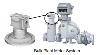
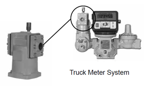
Most Liquid Controls mechanical air and vapor eliminators are shipped from the factory as part of a complete meter system. These air eliminators will arrive bolted to the top of a strainer on the inlet side of the meter.
Before the meter system can be put in operation, the vent ports of the air or vapor eliminator must be piped to a storage tank and/or a valve.
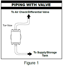
Piping to Storage TanksPiping configurations for Liquid Controls mechanical air and vapor eliminators are determined by two factors, (i) the presence or absence of a valve in the meter system and the presence or absence of bypass ports and (ii) a limited bleed valve plate in the mechanical air eliminator assembly. |
|
Piping to Air Check (or Differential) ValveFor meter systems installed into LPG applications, differential valves are often piped to the mechanical vapor eliminator in the Liquid Controls factory before shipment, but for other meter systems, the air eliminator will have to be piped in the field. |
 |
Piping Configurations & ConnectionsPiping configurations for Liquid Controls mechanical air and vapor eliminators are determined by two factors, (i) the presence or absence of a valve in the meter system and the presence or absence of bypass ports and (ii) a limited bleed valve plate in the mechanical air eliminator assembly. |
 |
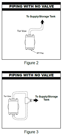
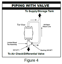
If the meter system has an air check or differential valve, the air or vapor eliminator and the valve must be piped together. If no air check or differential valve exists, you must either plug one of the vent ports (Figure 2) or pipe both vent ports to the storage tank (Figure 3). |
 |
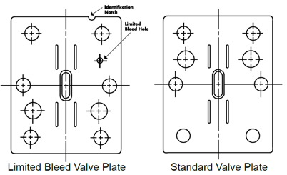
Air eliminator models cast without bypass ports cannot be assembled with a limited-bleed valve plate at the Liquid Controls factory. To retain the pressure control that a limited-bleed valve plate provides, a limited-bleed tee assembly must be installed in the piping between the air eliminator and the valve (Figure 4). |
|
Under normal circumstances, it is irrelevant which vent port is piped to the valve and which vent port is piped to the storage tank. However, there is one exception: air eliminators with an increased venting capacity valve plate. These include part numbers A8201, A8198, A8190, A8188, and A8183. When installing these air eliminators, the increased venting valve plate should be piped to the storage tank, and the limited-bleed valve plate should be piped to the valve. The limited-bleed valve plate is easily identified by the notch in the top of the plate (see below). |
 |
Piping Configuration |
The piping configuration for each air and vapor eliminator series is shown in the Bill of Materials. |
Electronic Valves |
When using an electronic valve, product may become trapped between the vapor eliminator and the valve. |
Piping Guidelines
•Pipe with as little restriction as possible. By minimizing restrictions, the air or vapor eliminator will work as efficiently as possible.
•¾" (or larger) pipe/hose is recommend to vent air or vapor to the storage tank.
•½" pipe/hose is recommended for piping to an air check or differential valve (⅜" is acceptable).
•If using hose, choose a type that will not collapse in on itself (heater hose, hydraulic hose, etc.).
•Be sure a catch vessel or spit receptacle is vented with a vent no smaller than the pipe/hose connected to it. (Catch vessels vary in size but most are between 2 and 5 gallons.)
•Pipe the air eliminator vent port into the top of the catch vessel for maximum efficiency.
•Liquid Controls recommends that catch vessels be drained regularly and that the volume is indicated with a sight gauge, for example.