Reassembling the Meter includes the following:
•Installing the meter
•Assembling the meter
•Timing the rotor gears and completing meter reassembly
•Reassembling the weldment Assembly
These charts are also available in the Torque Chart topic:
•Torque Chart
•Wrench and Socket Size Chart
Tools necessary for disassembly:
•Cover socket or open end/box end wrench
•Spare displacement rotor gear
•Rotor gear wrench or socket
•Bearing plate wrench or socket
NOTE: The principles of meter disassembly and reassembly are the same for all the Liquid Controls Positive Displacement meters. Although your meter may look slightly different than those pictured, the steps are the same except as noted.
Installing the Meter
Place the flat gasket in the lower weldment and line up the bolt holes. Position the meter housing in the weldment lower hemisphere and secure using the four bolts. Use care not to damage the flat gasket. Use an impact driver or socket to tighten bolts. |
 |
Assembling the Meter
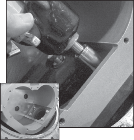
Step 1Install the blocking rotor. It will be necessary to guide the universal joint assembly into the drive coupling bearing and packing gland by reaching behind the meter element.
|

|
Step 2Install the two displacement rotors. Insert the nontapered ends into the housing. Place each rotor into its respective bore on the bearing plate. |
 |
Step 3Install the bearing plate cover over the three tapered ends and fasten it with the bearing plate screws. Use the bearing plate wrench. The number of screws varies between different meter sizes. |
 |
Step 4The rotors should have a small amount of end-play and be easy to turn. Test each rotor one at a time. Turn the rotors to make sure that they revolve freely. Jog the rotors from end to end to check for end-play. If they do not move easily in both tests, remove the rotors and check for burrs and corrosion deposits. Clean them thoroughly. Repeat steps 2, 3, & 4. |

|
Step 5Install the rotor keys. The rotor key is a small wedge of metal. Position the keys in each one of the three rotors. Press the keys into the rotor keyways. |
 |
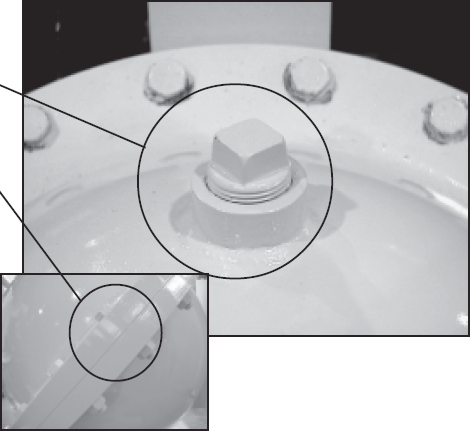
Timing the Rotor Gears
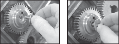
Rotor gears are timed by lining up the timing marks (circled in illustration). The blocking rotor gear has a tooth directly in front of its timing mark. On the displacement rotor gears, the timing mark falls in the space between two gear teeth. Ensure that the tooth in front of the timing mark on the blocking rotor gear connects with the space in front of the timing mark on the displacement rotor gear. You may need to remove the gears and reposition them several times on their rotor ends in order to get the timing marks to line up correctly. For more information, see Troubleshooting.
Follow this procedure:
Step 1Slide the blocking rotor gear on its tapered rotor end. Slide the right displacement rotor gear on its tapered rotor end so that the timing marks line up between the two gears.
HINT: Before placing the right displacement rotor gear on its end, hold the right rotor gear in position. Turn the blocking rotor gear. Line up the timing marks before placing the right displacement rotor gear on its tapered end.
|
 |
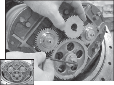
Slide the left displacement rotor gear on its tapered rotor end so that its timing mark lines up with the blocking rotor gear.
|
|
Step 2Insert the rotor gear screw and flat washer into each of the rotor gears and finger tighten.
|
|
Step 3Position the spare displacement rotor gear between the left displacement rotor and the blocking rotor gear to prevent the gears from moving. If a replacement gear is not available, use a shop rag between the teeth of the gears. Tighten the screws of the displacement rotor gears to the torque specification listed in the Torque Chart.
|
 |
Step 4Position the spare displacement rotor gear between the right displacement rotor and the blocking rotor gear to prevent the gears from moving. Tighten the screw of the blocking rotor gear to the torque specification listed in the Torque Chart.
Rotate the gears to make sure that the rotors turn freely. Burrs, foreign material, or marred surfaces can restrict the rotor movements. It may be necessary to remove the gears and rotors and deburr or clean the surfaces again. |
 |
Reassembling the Weldment Assembly
Follow this procedure:
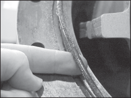
Step 1Install a new O-Ring in the groove around the weldment base assembly if required.
|
 |
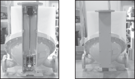
Step 2Position the weldment cover on top of the weldment base so that the cover vent plug is on top.
Install the screws around the rim of the weldment cover. Attach the nuts to the back of each screw. Begin by hand-tightening each of the screws. Once this is complete, tighten the nuts and bolts to the proper torque following the tightening sequence given in Bolt Tightening Sequence.
|
|
Step 3To complete the reassembly, reinstall the adjuster and drive components. When this is complete, reinstall the dust cover.
|
 |