This topic explains how to disassemble the meter, including how to:
•Remove non-corroded rotor gears
•Remove corroded rotor gears
•Remove the bearing plates and rotors
 |
RELIEVING INTERNAL PRESSUREAll internal pressures must be relieved before disassembly or inspection of the strainer, air eliminator, any valves in the system, the packing gland, and the front or rear covers. See “Relieving Internal Pressure” in Maintenance Requirements. |
These charts are also available in the Torque Chart topic:
•Torque Chart
•Wrench and Socket Size Chart
Tools necessary for disassembly:
•Rotor Gear Wrench or Socket
•Bearing Plate Wrench or Socket
•Counter Bracket Wrench or Socket
•Drain Plug Allen Wrench
•Cover Socket or Open End/Box End
•Spare Displacement Rotor Gear (if unavailable, use a shop rag between gear teeth)
•Plastic or Rubber Mallet
•2 Standard Screwdrivers
•Emery Cloth
•Wire Brush
Follow this procedure to begin disassembling the meter:
Step 1After the internal pressure has be relieved, open the drain plugs located at the bottom of the weldment assembly and discharge arm to drain all fluid from the weldment assembly.
|
|
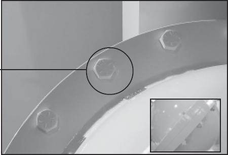
Step 2Once the system has been completely drained, the weldment assembly may be opened by removing the cover screws and bolts that are located around the rim of the enclosure. |
|
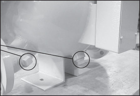
Step 3When all the screws and bolts have been removed, remove the weldment cover. This exposes the inside of the weldment assembly and provides access to the meter assembly. The meter assembly is held in place by 4 bolts on the inlet side of the meter. This can be either side of the meter depending on the direction of flow.
Access to these four bolts is gained by removing the front bearing plate of the meter housing.
|

|
Step 4Remove the O-Ring from the weldment assembly. Undamaged O-Rings may be reused. |
 |
Removing the Rotor Gears
If the gears show signs of corrosion, use the alternative method given in the section below.
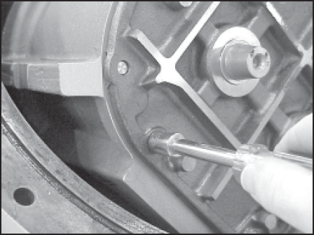
Step 1Hold a spare displacement rotor gear between the right displacement rotor gear and the blocking rotor gear to keep them from turning. If a spare gear is not available, use a shop rag between the gear teeth. Use the rotor gear allen key to loosen the rotor gear screw by turning it counter-clockwise. Do not remove the screw completely.
NOTE: Do not use a metallic tool for locking the gears as this will likely result in damage to the gear teeth.
|
 |
Step 2Keeping the spare displacement gear between the right rotor gear and blocking gear, use the Allen wrench to loosen the screw of the right rotor gear assembly. |

|
Step 3To loosen the screw of the blocking rotor gear, move the spare displacement rotor gear to between the left rotor gear and the blocking rotor gear to prevent the gears from moving. |

|
Step 4Once all the screws are loose, remove the screws and washers completely from each of the 3 gear assemblies. |
 |
Step 5Using one or two flat blade screwdrivers, gently pry the gear off its rotor tapered end. Do this for each of the gears. |
 |
As the rotor gear comes off, remove the key (1) from the rotor keyway (2). Save the key to use when reassembling. |
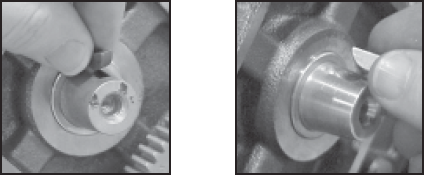
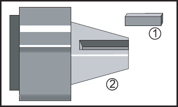
|
Removing the Bearing Plates and Rotors
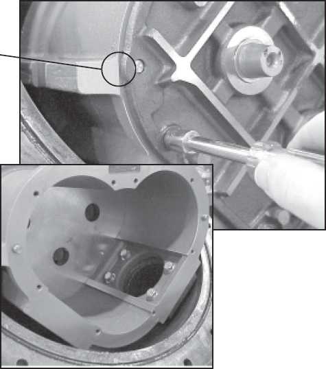
Step 1Use the bearing plate wrench or nut driver to remove the screws that hold the front bearing plate to the meter housing. The number of screws varies between the different meter sizes. |
|
Step 2When all the bolts are removed, insert a screwdriver into each of the two notches near the dowel pins. Be careful not to mar any of the surfaces. Gently pry the front bearing plate off the dowel pins. Remove the front bearing plate and rotor assemblies by pulling a rotor straight out from the housing. Be careful not to mar any of the surfaces.
|
|
Removing the Meter Housing Assembly
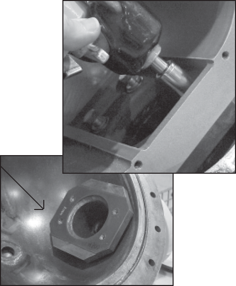
The meter housing assembly is held in place by four bolts. Remove these using an impact or socket wrench. There is a flat gasket between the meter housing and the weldment housing. Inspect this gasket for damage and replace as needed.
|
 |
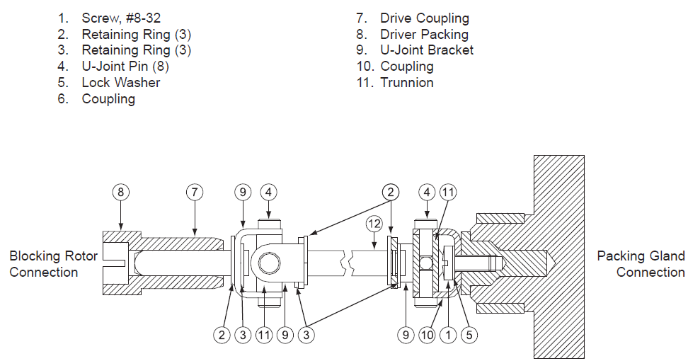
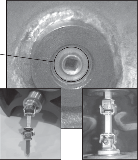
Universal Joint Assembly
The Universal Joint is an extension used to connect the blocking rotor of the meter to the packing gland. When the blocking rotor rotates, the Universal Joint causes the packing gland to rotate which drives the register. This assembly extends through the back of the meter and into the weldment wall through the drive coupling bearing.
|
 |
Universal Joint Components