Reassembling the Meter includes the following:
•Reassembling the bearing plates and rotors
•Timing the rotor gears and completing meter reassembly
These charts are also available in the Torque Chart topic:
•Torque Chart
•Wrench and Socket Size Chart
Tools necessary for disassembly:
•Cover socket or open end/box end wrench
•Spare displacement rotor gear
•Rotor gear wrench or socket
•Bearing Plate wrench or socket
NOTE: The principles of meter disassembly and reassembly are the same for all the Liquid Controls Positive Displacement meters. Although your meter may look slightly different than those pictured, the steps are the same except as noted.
Reassembling the bearing plates and rotors
Follow this procedure to begin disassembling the meter:
Step 1Rotor gears are on the front bearing plate. Install the non-rotor gear bearing plate using the bearing plate screws and wrench.
|
|
Step 2Insert the non-tapered ends of the three rotors into the housing from the opposite side. Place each rotor into its respective bore in the installed bearing plate. |
 |
Step 3Place the remaining bearing plate over the three tapered rotor ends and fasten it with the bearing plate screws. Use the bearing plate wrench. |
 |
Step 4The rotors should have a small amount of end-play and be easy to turn. Test each rotor one at a time. Turn the rotors to make sure that they revolve freely. Jog the rotors from end to end to check for end-play. If they do not move easily in both tests, remove the rotors and check for burrs and corrosion deposits. Clean them thoroughly. Repeat steps 2, 3, & 4. |
 |
Step 5The rotor key is a small wedge of metal. Each rotor has a notch–a keyway–to hold a key. Position a key into each one of the three rotors. Press the keys into the rotor keyways with your thumb and forefinger. |
 |
Step 6Slide the blocking rotor gear on its tapered rotor end. Slide the right displacement rotor gear on its tapered rotor end so that the timing marks line up between the two gears.
NOTE: Before you place the right displacement rotor gear on its tapered end, hold the right rotor gear in position. Turn the blocking rotor gear. Try to line up the timing marks before you place the right displacement rotor gear on its tapered rotor end.
|
 |
Position the left displacement rotor gear on its tapered rotor end so that its timing mark lines up with the blocking rotor gear. See the Timing the Rotor Gears section below.
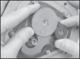
Timing the Rotor Gears
Rotor gears are timed by lining up the timing marks (circled in illustration). The blocking rotor gear has a tooth directly in front of its timing mark. On the displacement rotor gears, the timing mark falls in the space between two gear teeth. Ensure that the tooth in front of the timing mark on the blocking rotor gear connects with the space in front of the timing mark on the displacement rotor gear. You may need to remove the gears and reposition them several times on their rotor ends in order to get the timing marks to line up correctly. For more information, see Troubleshooting.
Step 1Position the spare displacement rotor gear between the left displacement rotor gear and the blocking rotor gear to prevent the gears from moving. Attach the right displacement gear washer and screw using the rotor gear wrench. Keep the spare displacement rotor gear positioned by the left displacement rotor gear. Attach the left displacement gear washer and screw using the rotor gear wrench. Tighten the screw to the torque specification in the Torque Chart.
|
|
Step 2Position the spare displacement rotor gear between the right displacement rotor gear and the blocking rotor gear. Attach the blocking rotor gear with the packing gland driver and screw using the rotor gear wrench. Tighten the screw to the torque specification listed in the Torque Chart. Rotate the gears to ensure that the rotors turn freely. It may be necessary to remove the gears and rotors and deburr and clean the surfaces again.
|
 |
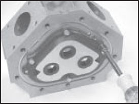
Step 3a. Install an o-ring (1) into the groove (2) on the front of the meter housing. b. Fasten the front cover (3) with the cover screws (4) using the cover socket or open end/box end wrench. c. Install an o-ring (8) into the groove (9) on the rear of the meter housing. Not shown; similar to (2). d. Fasten the rear cover (10) with the cover screws (11) using the cover socket or open end/box end wrench. e. Install POD5 Pulse Output Device. |
 |