This topic explains how to disassemble the meter, including how to:
•Remove non-corroded rotor gears
•Remove corroded rotor gears
•Remove the bearing plates and rotors
 |
RELIEVING INTERNAL PRESSUREAll internal pressures must be relieved before disassembly or inspection of the strainer, air eliminator, any valves in the system, the packing gland, and the front or rear covers. See “Relieving Internal Pressure” in Maintenance Requirements. |
These charts are also available in the Torque Chart topic:
•Torque Chart
•Wrench and Socket Size Chart
Tools necessary for disassembly:
•Rotor Gear Wrench or Socket
•Bearing Plate Wrench or Socket
•Counter Bracket Wrench or Socket
•Drain Plug Allen Wrench
•Cover Socket or Open End/Box End
•Spare Displacement Rotor Gear (if unavailable, use a shop rag between gear teeth)
•Plastic or Rubber Mallet
•2 Standard Screwdrivers
•Emery Cloth, Wire Brush
Follow this procedure to begin disassembling the meter:
Step 1Use the cover socket or open end/box end wrench to remove the bolts holding the front cover to the outer body. Remove the bolts holding the rear cover.
|

|
Step 2Remove the front and rear covers. |
 |
Step 3Remove the o-rings from the front and rear of the housing. Undamaged BUNA o-rings may be reused. |
 |
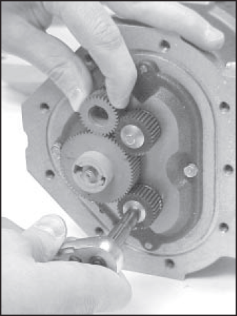
Step 4Hold a spare displacement rotor gear between the right displacement rotor gear and the blocking rotor gear to keep them from turning (if unavailable, use a shop rag between gear teeth). Use the rotor gear wrench or socket to remove the right displacement rotor screw and washer. |
 |
Step 5Hold the spare gear between the left displacement rotor gear and blocking rotor gear. Use the rotor gear wrench or socket to remove the screw and the packing gland driver held by the screw. |
 |
Step 6Hold the spare gear between the right displacement rotor gear and the blocking rotor gear. Use the rotor gear wrench or socket to remove the left displacement rotor gear screw and washer. |
 |
Removing Non-Corroded Rotor Gears
If the gears show signs of corrosion, use the alternative method given in the section below.
Step 1Insert two standard screwdrivers behind the blocking rotor gear. Gently pry the gear off its rotor tapered end. If the gear does not pry off easily, or feels stuck, use the alternative method given in the next section.
Use the same method to remove the left and the right rotor gears. Remember, if the gear does not pry off easily or feels stuck, use the alternative method given in the next section.
|

|
Step 2As each gear comes off the rotor, remove the key (1) from the rotor keyway (2). Save the key to use when reassembling the meter.
Use the bearing plate wrench to remove the bolts that hold the front bearing plate to the meter housing. On the back of the meter housing, remove the bolts that hold the rear bearing plate to the housing. Continue on to the section below, Removing the Bearing Plates and Rotors. |

|
Removing Corroded Rotor Gears
If the gears show signs of corrosion, use this method to remove the gears.
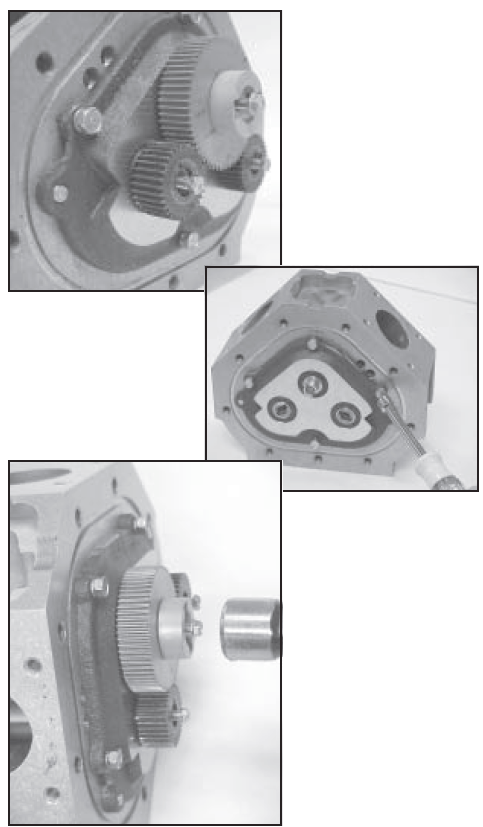
Step 1Replace all three rotor gear screws, without washers, halfway onto each of the rotor ends.
On the back of the meter housing, remove the screws that hold the rear bearing plate to the housing using the bearing plate wrench or socket.
With a plastic or rubber mallet, tap on the heads of the screws lightly and equally. As you tap on the screw heads, the gears are driven off the rotors. As the rotors are driven in, the rear bearing plate and the rotor assembly are pushed away from the housing. |
|
Step 2Use the bearing plate wrench or socket to remove the screws that hold the front bearing plate to the meter housing. Inspect and clean all critical surfaces like gear teeth, rotors and internal housing faces. Remove any crystalline formations using a fine emery cloth or a fine wire brush. Be careful not to mar or alter the shape of any of the parts. Changing the shape of parts may interfere with their operation. Remove nicks and burrs on metal parts with a stone. Remove all grit and other foreign particles. These may also damage parts and interfere with proper operation. Replace all parts that appear worn or damaged. |
 |
Removing the Bearing Plates and Rotors
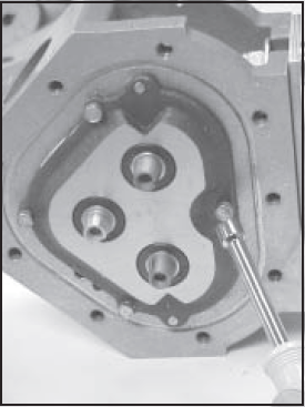
Step 1Insert a screwdriver into each of the two notches near the dowel pins. Be careful not to mar any of the surfaces. Gently pry the front bearing plate off the dowel pins.
|
 |
Step 2Remove the front bearing plate and rotor assembly by pulling a rotor straight out from the housing. Be careful not to mar any of the surfaces.
|
|
Step 3Remove the remaining bearing plate from the other side by inserting a screwdriver into each of the two notches near the dowel pins. Be careful not to mar any surfaces. Gently pry the rear bearing plate off the dowel pins. |
|

