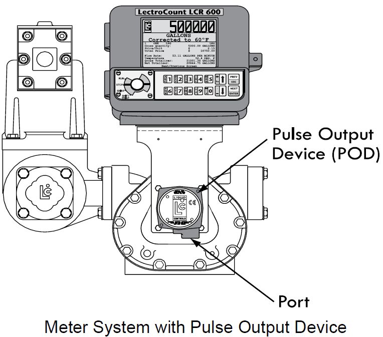
Pulse Output Device (POD) Installation
When ordered as part of a meter system with a LCR 600, Liquid Control’s Pulse Output Device (POD) is installed onto the meter and wired to the LCR 600 at the factory. The POD can also be ordered separately and installed onto meter systems already in service. For mechanical installation instructions, refer to the POD manual. Instructions for wiring the POD to the LCR 600 can be found.
Materials needed for wiring valves
These materials are necessary, but are not supplied with the valve:
•20 AWG stranded wire–3 per solenoid. Unnecessary for 3-way solenoid valves. Only 2 are necessary for E7 solenoids.
•Weatherproof flexible conduit, ½" diameter.
•½" NPT conduit connectors or cable glands.
•PTFE tape or pipe sealant.
Disconnect Power |
Disconnect the power before working on the CPU board. |
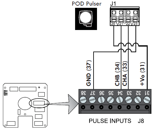
To wire a POD to the LCR 600:
1.Attach cable glands and/or conduit connectors to the POD and the LCR 600 port(s).
2.Thread the wires through a piece of weatherproof conduit cut-to-length from the POD port to a LCR 600 port.
3.Run the weatherproof conduit between the POD and the LCR 600 housing, pull the wires through the ports, and tighten the connectors.
4.Connect the four POD terminals to four terminals on the J18 terminal block of the LCR 600 CPU board.
•POD terminal 20 to LCR 600 terminal 31
•POD terminal 21 to LCR 600 terminal 34
•POD terminal 22 to LCR 600 terminal 33
•POD terminal 23 to LCR 600 terminal 37
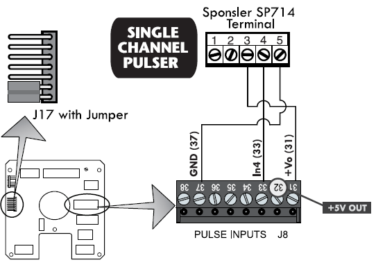
Single Channel Pulse Inputs
The LCR 600 is compatible with the many single channel pulsers and amplifiers. For example, the SP714 pulse amplifier.
Pulse Output Devices 1, 2, 3, & 4 Only |
This wiring schematic applies to pulse output devices 1 through 4 only. |
To wire a single channel pulse output to the LCR 600:
1.Slide the jumper over pins 2 & 3 (counting down from the top) of J17. The jumper fits over the pins and under the plastic casing.
2.Wire the single channel pulser to the J8 terminal of the 81920 CPU board. Schematic on the right shows wiring to a Sponsler SP714.