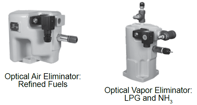
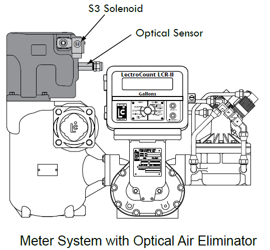
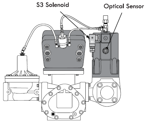
Optical Air and Vapor Eliminator Installations
When ordered as part of a meter system with a LCR 600, the Liquid Control optical air and vapor eliminators are bolted onto the strainer and wired to the LCR 600 at the factory. Optical air and vapor eliminators can also be ordered separately and installed onto meter systems already in service. For mechanical installation instructions, refer to the manual specific to the optical air and vapor eliminator. Instructions for wiring optical air and vapor eliminators to the LCR 600 are provided below.
Materials needed for wiring valves
These materials are necessary, but are not supplied with the valve:
•20 AWG stranded wire–3 per solenoid. Unnecessary for 3-way solenoid valves. Only 2 are necessary for E7 solenoids.
•Weatherproof flexible conduit, ½" diameter.
•½" NPT conduit connectors or cable glands.
•PTFE tape or pipe sealant.
To wire optical air and vapor eliminators to the LCR 600:
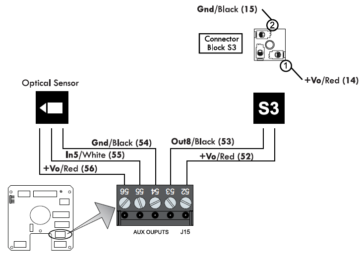
1.Attach cable glands and/or conduit connectors to the S3 solenoid valve, the optical sensor, and the LCR ports.
2.Thread the 20 AWG wires through a piece of weatherproof conduit cut-to-length from the S3 solenoid to a LCR 600 port.
3.Run the weatherproof conduit between the S3 solenoid operated valve and the LCR 600 housing. Pull the wires through the ports, and tighten the connectors. Liquid Controls recommends running the optical sensor wire through weatherproof conduit as well.
4.Connect the three 20 AWG wires to the S3 solenoid operated valve terminals and to terminals 52 and 53 on the J15 terminal block of the LCR 600 CPU board.
5.Connect the optical sensor wires to terminals 54, 55, and 56 on the J15 terminal block of the LCR 600 CPU board.
Disconnect Power |
Disconnect the power before working on the CPU board. |