The LectroCount® Large-Digit Remote Display can be used with the MASTERLOADx.iQ registers to provide long range visibility of either Flow Rate or Delivery Volume Quantity. In calibration mode, the LC Remote Display will display the Measured Quantity when Quantity is selected for LC Remote Display Value.
The sections below explain how to make the electrical connections and then configure the remote display.
Electrical Connections - Connecting the E1615 Remote Display to the E6000 MASTERLOADx.iQ Register
24V DC Power |
If the DC voltage to the LCR.iQ exceeds 24 V, the remote display must be powered from a separate DC-to-DC converter which provides 12 to 24 V. |
Follow these steps to connect the remote display to the E6000 register:
1.Open the LCR.iQ register.
2.Attach a cable gland to a port on the LCR.iQ electronic register.
3.Route the shielded cable through the cable gland and into the LCR.iQ register housing.
Shielded Cable |
The LectroCount XL LED Remote Display is supplied with a 30 foot 4-wire shielded cable with 22 gauge wire. If alternate cabling is required, Liquid Controls recommends a similar 4-wire shielded cable with 22 gauge wire or larger and a maximum cable length of 30 feet. |
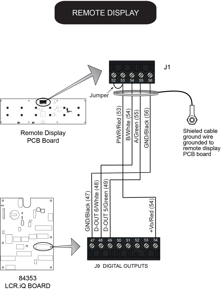
4.Connect the four wires of the display’s shielded cable to the four designated terminals on the J9 terminal block on the LCR.iQ CPU board:
• XL LED terminal 53 (red wire) to LCR.iQ terminal 54
• XL LED terminal 54 (white wire) to LCR.iQ terminal 48
• XL LED terminal 55 (green wire) to LCR.iQ terminal 49
• XL LED terminal 56 (black wire) to LCR.iQ terminal 47
J1 Jumper – LectroCount XL LED Remote Display |
For proper operation, install a jumper between terminal 52 and 53 on the display’s J1 terminal block. Display units from the factory include the jumper. Ensure the jumper is in place when rewiring the display. |
5.Tighten the cable gland and close the LCR.iQ register.
Configure the remote display
Follow these steps to configure the remote display:
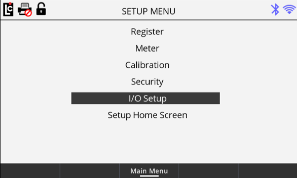
1.Navigate to the I/O Setup from the Setup Menu screen and press OK.
2.Navigate to the I/O Setup (4/4) screen.
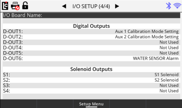
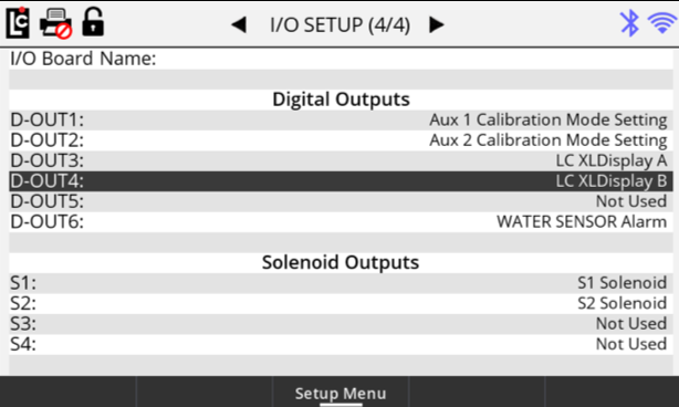
3.Select the D-OUT to which the Green wire is connected and set it to LC XLDisplay A.
4.Select the D-OUT to which the White wire is connected and set it to LC XLDisplay B.
5.Navigate to the Setup Menu screen and press OK.
6.Navigate to the Meter option and press OK.
7.Navigate to the Meter (3/3) screen.
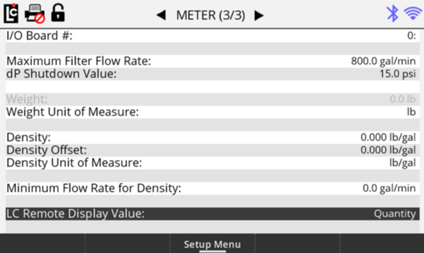
8.Select the LC Remote Display Value option and press OK.
9.Select either the Flow Rate or Quantity option.