I/O setup screen are used to setup and configure the various available inputs and outputs of the Register, and also activate and deactivate services such as printing, LCP communication, dP, Density and other sensing equipment.
I/O Setup (1/4)
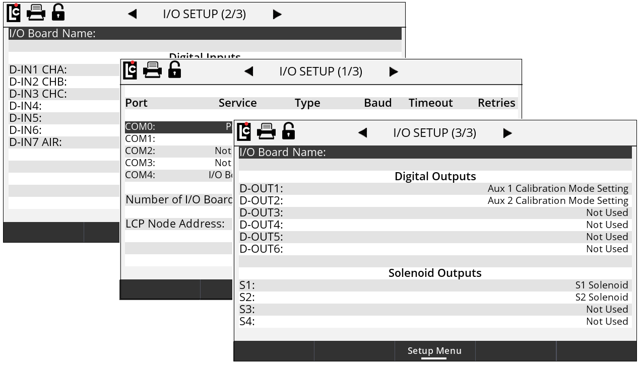
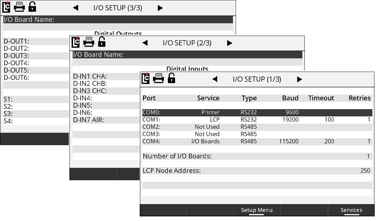
COM0 – COM4 – The Register has five serial ports. When one of the ports is selected, prompts for the Service, Type, Baud, Timeout, and Retries are shown. COM4 must be used with the I/O Boards service.
Service – A list box that permits the user to select between the services that have been enabled on the Services screen. Not Used can be selected to disable the use of the port.
Type – A list box permits the user to select between the types of serial communication for the serial port.
Options:
•RS232
•RS485
Baud – A list box that permits the user to select the baud rate for the serial port.
Options:
•2400
•4800
•9600 – This is the standard baud rate used for the Printer service.
•19200
•57600
•115200 – The I/O Boards service must use this baud rate.
Timeout – A numeric text field that shows the amount of time, in milliseconds, the Register will wait for a response, once a serial signal is sent out the port. This field is only used for the LCP and MASTERLOADx.iQ Network services.
Retries – After a serial signal has been sent out the port, if a response isn’t seen within the Timeout, this is the number of attempts the Register will attempt to retry sending the serial signal. This field is only used for the LCP and LCR.iQ Network services.
Number of I/O Boards – The number of I/O boards within the Register. The current limit is 1.
LCP Node Address – A numeric text field that shows the node address of the Register when communicating with a 3rd party device via the LCP service. (Minimum setting – 1, Maximum setting - 250)
Allow Pump & Print with LCP Host – A list box permits the user to select how the LCP service will behave.
Options:
•No – When the register receives an LCP message, the Start key will be disabled for 60 seconds. If the user wants to begin a delivery, it must be done through the 3rd-party device.
•Yes – The Start key on the register will not be disabled during LCP communication. This allows the user to always be able to begin a delivery from the register screen.
I/O Setup (2/4)
To utilize this functionality, first navigate to the Main Menu, then Setup Menu, then I/O Setup and I/O Setup 2/4.
To configure LCP over the Ethernet, select LCP Service on either ETH0 or ETH1. Then configure appropriate Network settings as follows:
1.Set the Network Mode to Station Mode.
2.Or, set the Network Mode to Station Mode with Static IP, and then select Network IP Address.
3.Tap Apply Network to apply these changes.
NOTE: Only one of the network interfaces either Wi-Fi or Ethernet can be enabled at time.
Details for the other settings in this screen are given below.
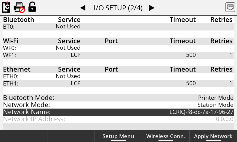
BT0 – The register has one Bluetooth port. Choosing this option will display prompts for the Service, Timeout, and Retries.
Service – A list box that permits the user to select between the services that have been enabled on the Services screen that can be used over Bluetooth.
Options:
•Not Used – This disables the use of Bluetooth.
•LCP – LCP communication over Bluetooth.
•Printer – To be used with a Bluetooth printer.
Timeout – A numeric text field that shows the amount of time, in milliseconds, the register will wait for a response, once a serial signal is sent out the port. This field is only used for the LCP service.
Retries – After a serial signal has been sent out the port, if a response isn’t seen within the Timeout, this is the number of attempts the register will attempt to retry sending the serial signal. This field is only used for the LCP service.
WF0 & WF1 – The register can establish two wi-fi connections. Choosing this option will display prompts for the Service, Timeout, and Retries.
Wi-Fi Mode – A list box permits the user to select which Wi-Fi Mode to use.
Options:
•Wi-Fi Direct – Does not require a wireless access point, allowing two devices to establish a direct Wi-Fi connection without requiring a wireless router.
•Wi-Fi Stationary – Requires a wireless access point to act as a hub for Wi-Fi communication.
SSID Name – An alpha-numeric text field that shows the service set identifier for the register. Other devices will use this name to identify the register and establish a connection. The default value begins with "LCR.iQ", which is followed by a unique identifier.
SSID Password – An alpha-numeric text field that shows the password for wireless communication with the Register. Other devices will use this password to establish a connection.
Wi-Fi Direct IP Address – The IP address of the register when in Wi-Fi Direct Mode.
Apply Wi-Fi – The user must press Apply Wi-Fi for any changes to the Wi-Fi Mode, SSID Name, SSID Password, or Wi-Fi Direct IP Address to take effect.
I/O Setup (3/4)
•Digital Inputs 1-7
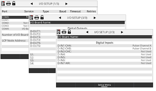
I/O Setup (4/4)
•Digital Outputs 1-6 and Solenoid Outputs S1-S4