Hardward Interfaces
•LCR.iQ Register
•I/O Board – Rev. J or greater
•SENSEiQ board (optional)
•Faudi Water Detector (or equivalent)
Basic Electrical Requirements
See hardware installation instructions.
Software Interfaces
4-20mA Analog Input
Setup
Follow these steps to setup the Water Level feature of the LCRiQ register:
Step 1 - Enter the Register Calibration mode by rotating the W&M screw counterclockwise.
Step 2 - Enable the Water Sensor service.
•Open the I/O Setup screen in the Setup Menu.
•Open the Services screen by pressing the Services hot key.

•Select the Water Service field by pressing the Up or Down keys, and then press Enter.
•Select Yes and press the OK key.
•Open the Sensor Setup screen by pressing Sensor Setup hot key.
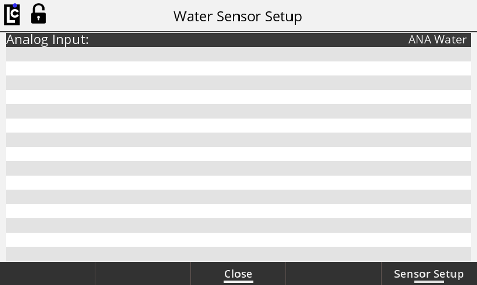
Step 3 - Setup the Water Service parameters for the Analog Port of the I/O or SENSEiQ board to which the water sensor connects. The water sensor uses the 4-20 mA current loop for operation. The register fields for the water sensor operation are accessible from Water Sensor Setup screen. Optionally, the water sensor configuration fields are accessible from the I/O Setup screen 3 for I/O board-or from I/O Setup screen 7 for the SENSEiQ board.
•Press the OK key and select desired analog input from the displayed list by pressing Up or Down keys. Select Analog ANA for the sensor connected to the I/O board, or ANA11 through ANA16 for sensor connected to SENSEiQ board. Press the OK key.
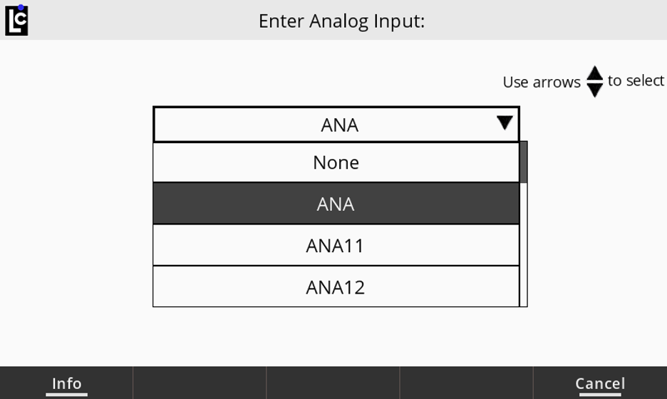
•Open the I/O Analog Input Setup screen by pressing the Sensor Setup hot key.
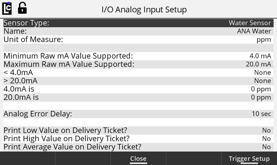
•Enter the Name of the input and press the OK key.
•Select the Unit of Measure field, and then select PPM as a unit of measure to be used for water level detection.
•Activate the alarm actions when the analog input current is out of the required range. To activate the alarm, select the <4mA or >20mA field and choose Error from the drop-down list. Press the OK key.
•Set the water level associated with a 4mA input current: Select the 4mA field, press the OK key, and then set the value of the water level, for example, to 0. Press the OK key.
•Set the water level associated with a 20mA input current: Select the 20mA field, press the OK key, and then set the value of the water level, for example, to 50. Press the OK key.
•Set the time in seconds required for the water level to continuously be at the selected level before the alarm actions will be activated. Select the Analog Error Delay field, press the OK key, and enter the time in a range from 0 to 10 seconds. Press the OK key.
•Choose which water levels that are detected during delivery will print on the delivery ticket. The average, low, or high levels can be printed by selecting the Yes options for those fields. Typically, high is set to Yes, and average and low are set to No.
•Open the I/O Analog Trigger Setup screen by pressing Trigger Setup hot key.
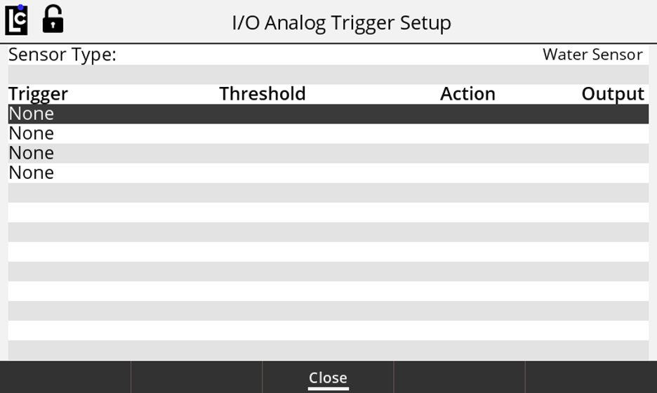
•Set the parameters of the first trigger to be used to monitor the water level during delivery:
- Select the first trigger field and press OK key.
- Specify if an action must occur when the water level is above or below the corresponding trigger level. Select the Above option from the drop-down list and press the OK key.
- Enter a trigger threshold of 15 and press the OK key.
- Select the delivery action to be taken when the trigger occurs. Select the Stop option from the drop-down list and press the OK key.
- Select the Digital Output of the I/O board to be used with the trigger: Outputs from 1 to 6 can be used. Ensure that the selected output has not been used for different actions of the register. Use the drop-down list to select the desired output.
•Set the parameters of the second trigger to be used to monitor the water level during delivery:
- Select the second trigger field and press OK key.
- Specify if an action must occur when the water level is above or below the corresponding trigger level. Select the Above option from the drop-down list and press the OK key.
- Enter a trigger threshold of 30 and press the OK key.
- Select the delivery action to be taken when the trigger occurs. Select the End option from the drop-down list and press the OK key.
- Select the Digital Output of the I/O board to be used with the trigger. The output should be the same as the one selected for the first trigger.
•If desired, select and configure another trigger. Up to 4 different triggers can be configured for the Analog Input of the I/O board.
•Complete the Analog Input Setup by pressing the Close hot key.