The Liquid Controls Pulse Output Device (POD) converts the rotary motion of the Positive Displacement Meter into electronic pulses, making it possible to interface the meter to electronic monitoring and control equipment. The POD5 was specifically designed to interface with the MA4 meter and the SCAMP A™ electronics.
The POD5 mounts directly to the front cover of the MA-4 meter. The motion of the meter blocking rotor is magnetically coupled through a stainless steel wall into the electronics compartment of the POD5. This eliminates any dynamic seal and isolates the electronics from the process fluid in the meter.
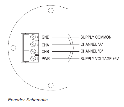
Inside the POD5 electronics compartment, an optical shaft encoder converts the rotary motion into a high resolution, two-channel quadrature square wave. Both outputs switch from 5 volts in the ON state to zero volts in the OFF state.
The POD5 electronics compartment also serves as a conduit junction box. The POD5 has an O-Ring sealed, threaded cover. The standard wire entrance is a 1/2-14 NPT female hub, which accepts threaded conduit or a cable gland. A plug-in connector on the encoder facilitates wiring of the unit. With the wiring entrance sealed and the cover in place, the housing is ENCLOSURE TYPE NEMA 4X, weatherproof rated. In addition, the housing is CENELEC rated flameproof, and UL and Canadian-UL explosion-proof rated when properly installed with approved conduit.
Installation
The POD5 comes factory installed on the meter ready for wiring with the conduit orientation in the up position.
The hub can be oriented in one of four possible directions; facing up, down, left, or right. If a different orientation is necessary, remove the two mounting screws and pull the POD5 from the front cover. Remove the POD5 O-ring from the cover.
Follow these steps:
1.After determining the orientation of the conduit hub, determine which two of the four mounting screw holes will be used to fasten the POD5 to the front of the meter cover. It is suggested that the mounting screws be driven into these holes first to “pre-tap” the threads in the meter cover. This will make it easier to thread the screws when the POD5 is in place.
2.Position the O-ring on the bottom of the POD5.
3.Align the fork driver to the drive mechanism inside the meter and guide the POD5 into the opening in the meter cover. When the driver is properly aligned the POD5 will go in until its mounting flange abuts the meter cover.
4.Rotate the POD5 to the desired orientation and thread in the mounting screws finger tight. Using a 5/16-inch box-end wrench, tighten the screws to the appropriate torque as specified in the Torque Chart.
Wiring
Wiring into the POD5 must enter through its conduit hub. For explosion-proof rated installations (Class I, Div. 1) the wiring must be enclosed in rigid conduit that is rated for explosion-proof installation. The conduit must be engaged five (5) full threads into the female hub on the POD5 to meet explosion-proof standards. When a Division 2 installation is called for, either rigid conduit, flexible conduit such as LiquidTight (or no conduit) can be used. When no conduit is used, the instrument cable must be brought into the conduit hub using a cable gland to seal the wiring entrance to maintain the ENCLOSURE TYPE 4X rating. Irrespective of the type of conduit/cable gland used, thread sealant should be applied to prevent moisture from getting into the POD5 electrical housing.
Removing the cover of the POD5 will expose the plug-in connector and ground screw.
Service Information
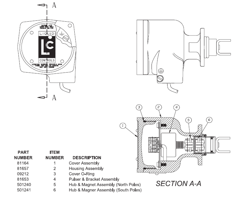
Due to the simplicity of the POD5, there are few things that can go wrong with the device. However, as with all electronic devices, failures can occur making it necessary to replace failed part(s). There are only three functional spare parts for the POD5: (a) the hub/magnet assembly-North Poles, (b) hub/magnet assembly-South Poles, and (c) the encoder assembly. The South Pole hub/magnet assembly operates inside the flowmeter and, therefore, is made wet by the process fluid. Due to its materials of construction, this assembly is unlikely to fail. In the event that it does fail, the POD5 has to be removed from the meter front cover to access the driver/ lower magnet assembly. |
 |
Remove the POD5 from the meter by removing the two hex head mounting screws and pulling out the POD5.
Remove the two allen-head set screws using a 1/16-inch hex driver and pull on the driver tang to extract the driver / lower magnet assembly. Disassemble the hub/magnet assembly from the drive shaft and attach the new hub / magnet assembly in its place. Reassemble the unit.
It is more likely that if a failure of the POD5 occurs, it can be repaired by replacing the encoder assembly. Simply turn off the power to the unit, open the cover, disconnect the electrical connector, loosen the mounting screws and pull the encoder assembly out. Remove the hub/magnet assembly from the old encoder shaft. Reassemble the new encoder assembly.
Use correct hub/magnet assemblies |
It is important to use the correct hub/magnet assemblies to maintain the magnetic couple. Use of two North Pole or two South Pole assemblies will not allow the driver to function properly. |
Voltage Supply |
(V+): 5VDC |
Current Supply |
26 mA (typical) |
Output Signal Resolution |
100 pulses per encoder revolution per channel, upscaled. |
Square Wave |
Dual quadrature channel output. |
Pulse Timing |
Nominal 50% on, 50% off. |
Rise/Fall Time of Pulse |
5 microseconds maximum. |
Output |
Capable of driving one TTL input (0 to 5 volts) |
Operating Temperature |
-40ºF to +185ºF (-40ºC to +85ºC) |
Humidity Range |
0-100% non-condensing |
Shock |
50 G’s for 10 milliseconds |
Vibration |
1 G at 10-150Hz |
Electromagnetic Compatibility |
(EMI, RFI, etc.) to CE standards |
Pulse Transmission Distance |
Up to 100 feet |