When you have made all of the data connections and complete installation of all components, connect the power to the LCR 600 and the Epson printer. Before making the power connections, go through the vehicle system checklist below, and ensure that the electrical system of the truck meets the minimum requirements for powering the LCR 600 and the Epson printer.
Vehicle System Checklist
•Clean any corrosion from the battery terminals and battery cable to guarantee a solid, tight connection.
•Charge the battery according to manufacturer specifications.
•Ensure the alternator is large enough to meet the total demands of the truck, including the LCR 600. The LCR 600 requires a minimum of 5 Amps for proper operation. Run the truck at low idle, with all accessories on (including hose reel). Then check the voltage with a multimeter. The voltage should not drop below 11 Volts.
•Inspect the electrical equipment on the vehicle to ensure proper installation and operation.
•Determine whether the vehicle is grounded positively or negatively. Consult Liquid Controls if the vehicle has a positive ground.
•Ensure that any radio antennas are installed according to manufacturer specifications to prevent RF interference.
Connect the Power
All LCR 600 shipments typically include a 40-foot gray power cable (100-foot, and 300-foot are also available) and a 7.5 Amp fuse.
Cable routing |
Routing Data and Power Cables describes the best practices for routing the gray power cable to the truck cab’s accessory panel. |
40-foot Gray Power Cable
The gray power cable (PN 84046) is prewired to the J6 terminal on the CPU board at the factory. It includes two 16AWG wires and a ground drain wire. The 7.5 Amp fuse should be spliced into the red 16AWG wire as close to the power source as possible.
Epson Printer Power
Power must also be supplied to the Epson printer. For supplying power to the printer, a 15-foot cable with a 12/24VDC converter (825001) is also available. The red wire of this cable must be spliced into the red wire in the gray power cable on the LCR 600 side of the 5 Amp fuse.
To connect power to the LCR 600 and the Epson printer:
1.Route the gray power cable to the accessory panel. See Routing Data and Power Cables.
2.Splice the red wire from the printer power cable into the red wire of the gray power cable.
3.Splice the 7.5 Amp fuse into the red wire. Make the splice close to the direct power terminal connection in the accessory panel, and on the power side of the splice made with the printer power cable.
4.Connect the red wire to the direct power supply terminal in the accessory panel.
5.Connect the black wire of the gray power cable to a reliable DC ground.
6.Connect the black wire of the printer power to a reliable DC ground.
7.Tape the green drain wire of the gray power cable back against the power cable.
Power Check
After the LCR 600 has been installed, check to ensure that it powers up correctly. The LCR 600 display and the printer power light should come on when the truck ignition is turned either to the ON position or the ACC position. Ensure that the printer power switch is on. If the LCR 600 or the printer does not power up, check the wiring and the connections on the LCR 600 CPU board against the instructions in this manual.
Epson Printer Power Connections
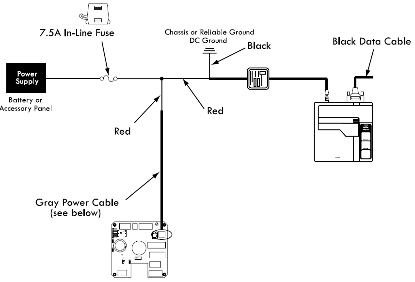
LectroCount LCR 600 Power Connections
