Optical Air and Vapor Eliminator Installations
When ordered as part of a meter system with a Register, the Liquid Control optical air and vapor eliminators are bolted onto the strainer and wired to the Register at the factory. Optical air and vapor eliminators can also be ordered separately and installed onto meter systems already in service. For mechanical installation instructions, refer to the manual specific to the optical air and vapor eliminator. Instructions for wiring optical air and vapor eliminators to the Register are provided below.
Optical Air Eliminator (Refined Fuels) 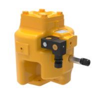 |
Optical Vapor Eliminator (LPG and NH3) 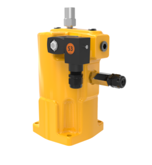 |
Materials needed for wiring valves
These materials are necessary, but are not supplied with the valve:
•20 AWG stranded wire–3 per solenoid. Unnecessary for 3-way solenoid valves. Only 2 are necessary for E7 solenoids.
•Weatherproof flexible conduit, ½" diameter.
•½" NPT conduit connectors or cable glands.
•PTFE tape or pipe sealant.
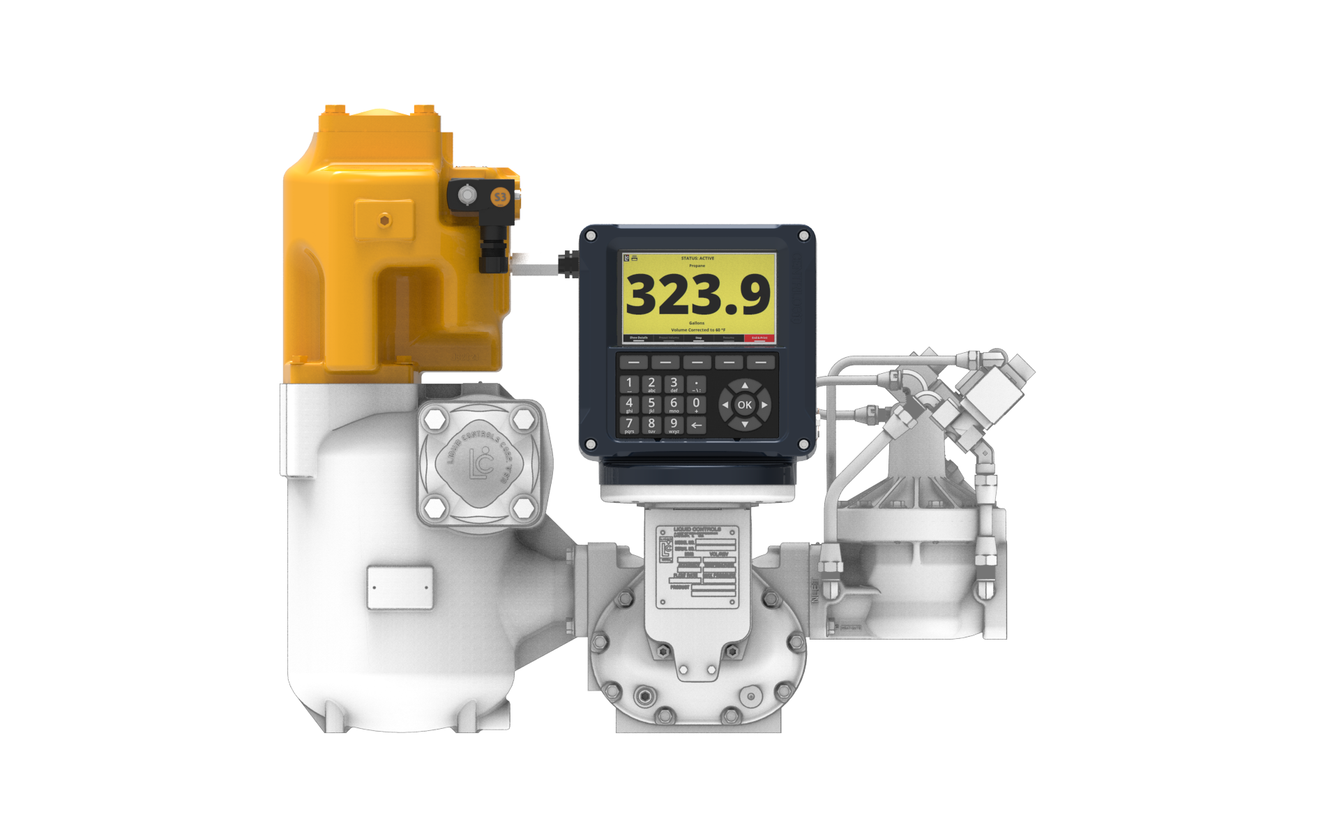
M7 meter system with optical air eliminator
Wire optical air and vapor eliminators to the Register
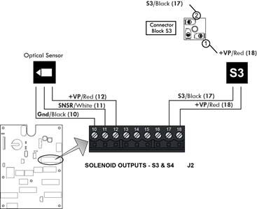
Refer to the figure below, and follow these steps:
1.Attach cable glands and/or conduit connectors to the S3 solenoid valve, the optical sensor, and the Register ports.Be sure to use thread sealant on NPT threads.
2.Thread the 20 AWG wires through a piece of weatherproof conduit cut-to-length from the S3 solenoid to a Register port
3.Run the weatherproof conduit between the S3 solenoid operated valve and the Register housing. Pull the wires through the ports, and tighten the connectors. Liquid Controls recommends running the optical sensor wire through weatherproof conduit as well.
4.Connect the two 20 AWG wires to the S3 solenoid operated valve terminals and to terminals 17 and 18 on the J2 terminal block of the Register board.
5.Connect the optical sensor wires to terminals 10, 11, and 12 on the J2 terminal block of the Register board.
Disconnect Power |
Disconnect the power before working on the CPU board. |
New Installations - Air Eliminators
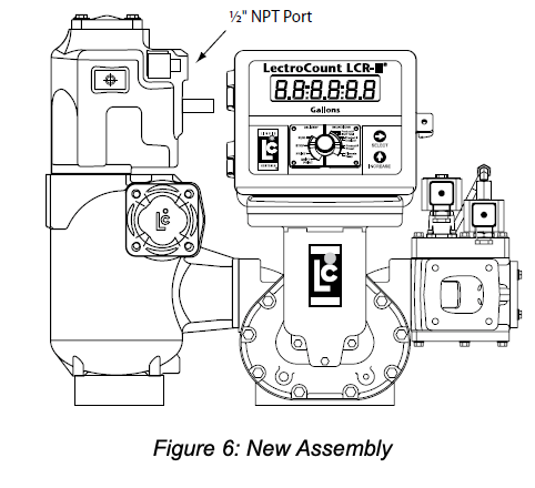
When ordered with a new meter, the optical air eliminator is mounted atop a strainer on the inlet side of the meter. An example is the meter with high-capacity strainer, two-stage valve, and Lectro-Count LCR-II® Electronic Register shown in the Figure 6.
A vent line must be connected from the output port of the optical air eliminator. This connection is ½” NPT. The vent line must be connected to an appropriate receptacle, such as an overflow tank on a truck.
The optical air eliminator solenoid valve and optical sensor are supplied pre-wired to the Lectro-Count Electronic Register. |
 |
Retrofit Installations
Depending on the existing configuration, adding an optical air eliminator valve may require modification of the vent piping, modification or change of the outlet valve, and/or modification or change of the register.
The optical air eliminator requires the following components to operate:
•Lectro-Count LCR/LCR-II Electronic Register, with internal CPU board Part Number 81920 or LC³ with CPU board Part Number 81924.
•Electronically-controlled outlet valve such as the A2982-11 or A2848-11.
Refer to the manuals accompanying these items for proper installation and configuration. Read the warning below, and then continue on to the instructions for retrofitting an old air eliminator.
 |
RELIEVING INTERNAL PRESSUREAll internal pressure must be relieved to zero pressure before disassembly or inspection of the strainer, vapor eliminator, any valves in the system, the packing gland, and the front or rear covers. Serious injury or death from fire or explosion could result in performing maintenance on an improperly depressurized and evacuated system. Strictly follow this procedure Relieving Internal Pressure Procedure for LPG and NH3 Meters: 1.Close the belly valve of the supply tank. 2.Close the valve on the vapor return line. 3.Close the manual valve in the supply line on the inlet side of the meter. If no manual valve exists on the inlet side, consult the truck manufacturer for procedures to depressurize the system. 4.Slowly open the valve/nozzle at the end of the supply line. 5.After product has bled off, close the valve/nozzle at the end of the supply line. 6.Slowly crack the fitting on top of the differential valve to relieve product pressure in the system. Product will drain from the meter system. 7.As product is bleeding from the differential valve, slowly reopen and close the valve/nozzle on the discharge line. Repeat this step until the product stops draining from the differential valve and discharge line valve/nozzle. 8.Leave the discharge line valve/nozzle open while working on the system. |
These retrofit instructions will indicate a system using a Hi-Cap strainer/air eliminator. However, the optical air eliminator may also be installed on other LC strainer assemblies used for refined petroleum products.
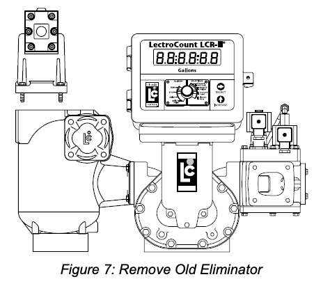
Step 1 - Remove Old Air Eliminator and Baffel CupAfter the internal pressure has been relieved from the system and the assembly drained of liquid, remove the four bolts and washers used to fasten the old air eliminator to the top of the strainer. Inspect the O-ring and replace if necessary.
|
 |
Step 2 - Mount the Optical Air EliminatorDepending on the strainer being used, the optical air eliminator may be fastened to the strainer/air eliminator in any of four 90° rotational increments. Select the most suitable orientation for ease of final installation of wiring and vent piping.
Fasten the optical air eliminator to the strainer using the four bolts and washers. Tighten the bolts to a torque of 27 lbf-ft (37 Nm).
|

|
Step 3 - Connect the Vent Piping/TubingThis connection is ½” NPT. Remove the pipe thread protector and then connect the piping/tubing to the vent port. This piping typically connects directly to an overflow tank on a truck.
Step 4 - Wire the Solenoid and Sensor to the RegisterThe wiring instructions are given in below.
|
 |
Wiring
|
WARNINGIncorrect wiring can damage the optical sensor.
For North American Installations, the installation must be fully in accordance with the National Electrical Code (US) or the Canadian Electrical Code respectively to maintain the hazardous location ratings on the product. This may involve using rigid conduit for all connections. |
The optical air eliminator requires a Lectro-Count LCR/ LCR-II Electronic Register with CPU board part number 81920 (LC³ with 81924). If the LectroCount does not contain an 81920 CPU board (LC³ with 81924), this board must be ordered as a replacement to the existing CPU board.
The 81920 CPU board has an additional connector, connector J15, not present on other board models. On the LC³ 81924 CPU board, it is connector J11.
To make the connection to a Lectro-Count Register, the optical sensor comes supplied with a 24-inch cable. The cable is potted in the optical sensor assembly at one end. A threaded cord grip is included to fasten the other end of the cable into the back of the Lectro-Count Register. The solenoid requires a 12 AWG, two-wire, braided cable, approximately 24 to 36” in length.
|
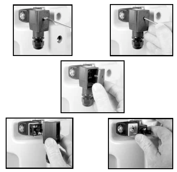 |
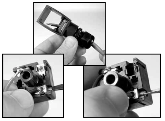
Step 1 - Remove Cable PlugLoosen and remove the screw from the cover of the S3 solenoid valve cable plug. Remove the cable plug from the solenoid valve coil. Remove the cover from the cable plug housing and then remove the terminal block. Be sure to note its orientation in the housing. Leave the flat gasket in place on the coil.
Step 2 - Connect Cable to Cable PlugRoute one end of the cable through the conduit fitting and into the cable plug housing. Connect the cable wires to the terminal block. Connect the BLACK wire to Terminal 2 and the RED wire to Terminal 1. These indicators are marked on the terminal block.
|
 |
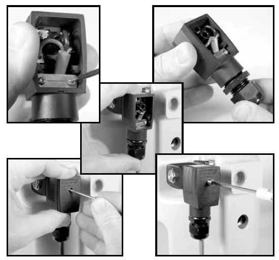
Step 3 - Reassemble Cable PlugReinstall the terminal block into the cable plug housing in the same orientation you found it. Tighten the strain relief strap inside the cable plug using the two screws. Tighten the cable gland on the bottom of the cable plug so that it seals around the cable.
Reconnect the cable plug to the coil. Place the cover over the cable plug and fasten with the screw to a torque of 8.8 in-lbs (1 Nm).
Step 4 - Connect to Lectro-Count Electronic RegisterRoute the cables from the optical sensor and solenoid valve to the back of the Lectro-Count register. Connect these to two open ports on the back of the register using the appropriate connectors. |
 |
LCR-II ConnectionsConnect the wires to terminal block J15 on the Lectro-Count CPU board. Refer to Figure 11a for additional clarification.

 |
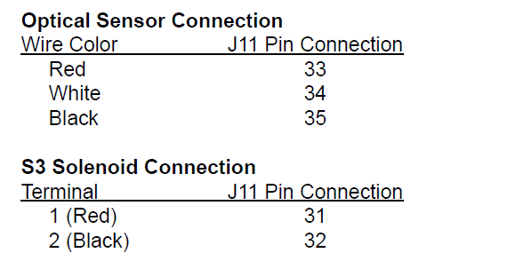
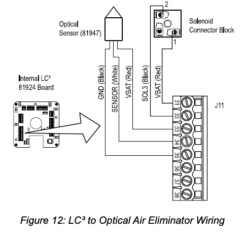
LC3 ConnectionsConnect the wires to terminal block J11 on the Lectro-Count CPU board. Refer to Figure 11b for additional clarification.
 |
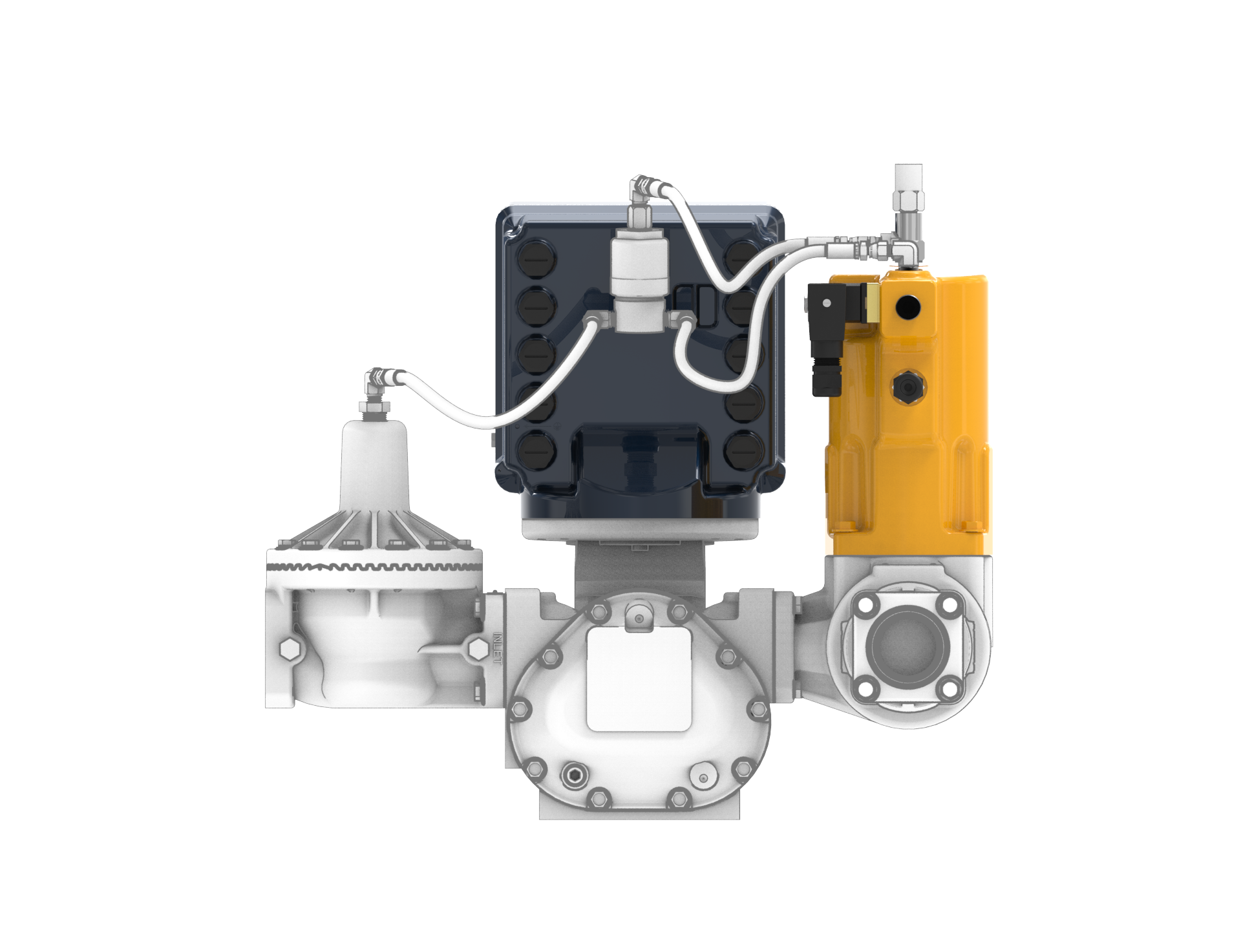
New Installations - Vapor Eliminators
When ordered with a new meter, the optical vapor eliminator is mounted atop a strainer on the inlet side of the meter. An example is the meter with high-capacity strainer, two-stage valve, and Lectro-Count LCR-II® Electronic Register shown in the Figure 6.
A vent line must be connected from the output port of the optical vapor eliminator. This connection is ½” NPT. The vent line must be connected to an appropriate receptacle on a supply or storage tank.
The optical vapor eliminator solenoid valve and optical sensor are supplied pre-wired to the Lectro-Count Electronic Register. |
|
Retrofit Installations
Depending on the existing configuration, adding an optical vapor eliminator valve may require modification of the vent piping, modification or change of the outlet valve, and/or modification or change of the register.
The optical vapor eliminator requires the following components to operate:
•Lectro-Count LCR/LCR-II Electronic Register, with internal CPU board Part Number 81920 or 84040m or LC³ with CPU board Part Number 81924, or LCR 600 with CPU board 84040.
•Electronically-controlled outlet valve.
Refer to the manuals accompanying these items for proper installation and configuration. Read the warning below, and then continue on to the instructions for retrofitting an old vapor eliminator.
|
RELIEVING INTERNAL PRESSUREAll internal pressure must be relieved to zero pressure before disassembly or inspection of the strainer, vapor eliminator, any valves in the system, the packing gland, and the front or rear covers. Serious injury or death from fire or explosion could result in performing maintenance on an improperly depressurized and evacuated system. Strictly follow this procedure Relieving Internal Pressure Procedure for LPG and NH3 Meters: 1.Close the belly valve of the supply tank. 2.Close the valve on the vapor return line. 3.Close the manual valve in the supply line on the inlet side of the meter. If no manual valve exists on the inlet side, consult the truck manufacturer for procedures to depressurize the system. 4.Slowly open the valve/nozzle at the end of the supply line. 5.After product has bled off, close the valve/nozzle at the end of the supply line. 6.Slowly crack the fitting on top of the differential valve to relieve product pressure in the system. Product will drain from the meter system. 7.As product is bleeding from the differential valve, slowly reopen and close the valve/nozzle on the discharge line. Repeat this step until the product stops draining from the differential valve and discharge line valve/nozzle. 8.Leave the discharge line valve/nozzle open while working on the system. |
To retrofit an optical vapor eliminator:
Step 1 - Remove Old Vapor Eliminator and Baffel CupAfter the internal pressure has been relieved from the system and the assembly drained of liquid, remove the four bolts and washers used to fasten the old vapor eliminator to the top of the strainer. Inspect the O-ring and replace if necessary.
|
|
Step 2 - Mount the Optical Vapor EliminatorDepending on the strainer being used, the optical vapor eliminator may be fastened to the strainer/vapor eliminator in any of four 90° rotational increments. Select the most suitable orientation for ease of final installation of wiring and vent piping.
Fasten the optical vapor eliminator to the strainer using the four bolts and washers. Tighten the bolts to a torque of 27 lbf-ft (37 Nm).
|
|
Step 3 - Connect the Control Piping/Tubing for LPGMake plumbing connections from the 3-way solenoid valve assembly to vapor eliminator and differential valve assembly. Follow the lettered designations in Figure 10.
|
 |
Step 4 - Wire the Solenoid and Sensor to the RegisterThe wiring instructions are given in below. |
|
Wiring
|
WARNINGIncorrect wiring can damage the optical sensor.
For North American Installations, the installation must be fully in accordance with the National Electrical Code (US) or the Canadian Electrical Code respectively to maintain the hazardous location ratings on the product. This may involve using rigid conduit for all connections. |
The electrical installation of the optical vapor eliminator includes connecting the S3 solenoid and the optical sensor to the LectroCount register.
The optical sensor has a 24” cable potted to the inside the optical sensor assembly at one end. The other end of the cable has a threaded cord grip that fastens into the back of the LectroCount® register.
The S3 solenoid-operated valve requires a 12 AWG, two-wire, braided cable, approximately 24 to 36” in length.
|
|
The S3 solenoid-operated valve requires a LectroCount® LCR/LCR-II electronic register with CPU board part number 81920 or 84040 (LC³ with 81924). If the LectroCount® does not contain a proper CPU board (LC³ with 81924), replacement CPU boards can be ordered.
Both the 81920 and 84040 CPU board have an additional terminal, J15 (J11 on the LC³ 81924 CPU board). The extra terminal vital for operating the optical vapor eliminator, and it is not present on other board models.
Follow these steps to wire the S3 solenoid and the optical sensor:
Step 1 - Remove Cable PlugLoosen and remove the screw from the cover of the S3 solenoid valve cable plug. Remove the cable plug from the solenoid valve coil. Remove the cover from the cable plug housing and then remove the terminal block. Be sure to note its orientation in the housing. Leave the flat gasket in place on the coil.
Step 2 - Connect Cable to Cable PlugRoute one end of the cable through the conduit fitting and into the cable plug housing. Connect the cable wires to the terminal block. Connect the BLACK wire to Terminal 2 and the RED wire to Terminal 1. These indicators are marked on the terminal block.
|
|
Step 3 - Reassemble Cable PlugReinstall the terminal block into the cable plug housing in the same orientation you found it. Tighten the strain relief strap inside the cable plug using the two screws. Tighten the cable gland on the bottom of the cable plug so that it seals around the cable.
Reconnect the cable plug to the coil. Place the cover over the cable plug and fasten with the screw to a torque of 8.8 in-lbs (1 Nm).
Step 4 - Connect to Lectro-Count Electronic RegisterRoute the cables from the optical sensor and solenoid valve to the back of the Lectro-Count register. Connect these to two open ports on the back of the register using the appropriate connectors. |
|
LC3 Wiring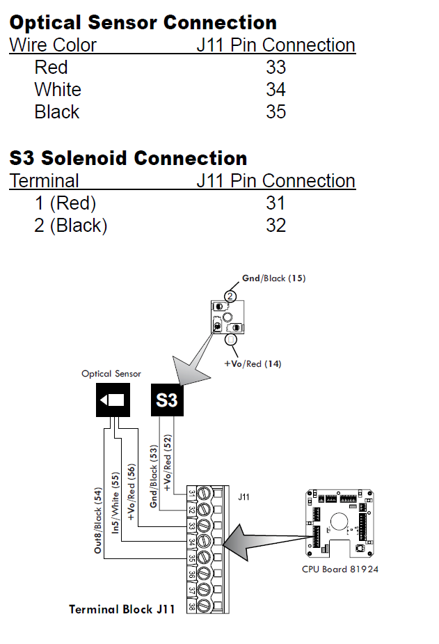 |
LCR Wiring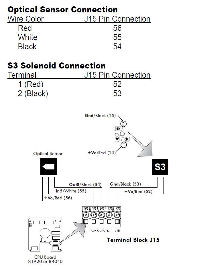 |