 |
RELIEVING INTERNAL PRESSUREAll internal pressure must be relieved to zero pressure before disassembly or inspection of the strainer, vapor eliminator, any valves in the system, the packing gland, and the front or rear covers. Serious injury or death from fire or explosion could result in performing maintenance on an improperly depressurized and evacuated system. Strictly follow this procedure Relieving Internal Pressure Procedure for LPG and NH3 Meters: 1.Close the belly valve of the supply tank. 2.Close the valve on the vapor return line. 3.Close the manual valve in the supply line on the inlet side of the meter. If no manual valve exists on the inlet side, consult the truck manufacturer for procedures to depressurize the system. 4.Slowly open the valve/nozzle at the end of the supply line. 5.After product has bled off, close the valve/nozzle at the end of the supply line. 6.Slowly crack the fitting on top of the differential valve to relieve product pressure in the system. Product will drain from the meter system. 7.As product is bleeding from the differential valve, slowly reopen and close the valve/nozzle on the discharge line. Repeat this step until the product stops draining from the differential valve and discharge line valve/nozzle. 8.Leave the discharge line valve/nozzle open while working on the system. |
Disassembly
The optical vapor eliminator consists of a housing, optical sensor, and control solenoid valve. Of these three components, only the solenoid valve is serviceable. However, if any part of the solenoid is damaged, a new solenoid assembly (Part Number 502011) must be ordered. The optical sensor contains no serviceable parts because the internal components are potted. If the optical sensor fails, the complete assembly must be replaced (Part Number 81947).
Tools necessary for disassembly:
•Flat blade screwdriver
•14mm box end or open end wrench
Follow the steps below to disassemble the S3 solenoid:
Step 1Loosen the thin hex nut holding the solenoid in place using a 14mm wrench. Remove the nut and coil from of the armature guide post.
|

|
Step 2Remove the plastic bonnet from the armature guide post. This should be easy to remove without tools. |
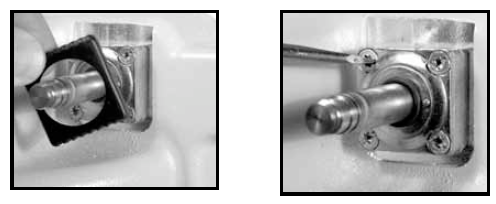 |
Step 3Using a screwdriver, loosen the upper-left and lower-right screws of the valve body. These are the only two screws which hold the valve body in place. The upper right and lower left screws fasten the armature guide post and valve body together. Remove the valve body from the optical vapor eliminator housing. |
|
Step 4Place the valve body on a flat surface. Using a flat blade screwdriver, remove the two screws which hold the armature guide post and valve body together. Lift the armature guide post off of the valve body. The internal components consist of a plunger and a spring. Inspect the spring for damage.
|

|
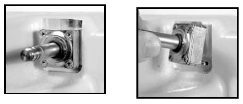
Step 5The armature guide post consists of four components: two O-rings, the guide post, and the flange. Inspect these components for damage. The valve body has two O-rings found on the face that butt against the housing. The two O-rings are identical. Inspect them for damage. Inspect the ports for blockage.
|
 |
Reassembly
Step 1Place the spring inside the plunger and insert the plunger, spring end first, into the armature guide post. Place the armature guide post assembly on the valve body.
Fasten the armature guide post to the valve body using the two screws removed earlier. Two holes of the valve body are threaded and two are not. Ensure the screws insert properly into the threaded holes.
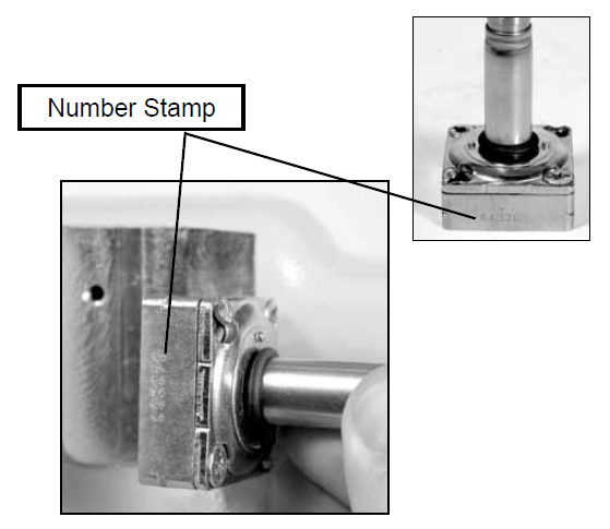
Look closely to see that the valve body has a number stamped into it. This will be used to set the proper orientation of the solenoid valve body with respect to the optical vapor eliminator housing assembly.
|
 |
Step 2Align the solenoid valve body such that the stamped number on the valve body faces the housing assembly, as shown in the image to the left. The valve body can physically be fastened to the housing assembly in one of two orientations. Only one orientation is correct.
IMPORTANT: If the stamped numbers face away from the housing, the optical vapor eliminator will not function properly. The port will be blocked and the eliminator will fail.
With the valve body in the proper orientation, fasten it to the housing using the two screws removed previously. Tighten to a torque of 15 to 18 in-lbs (1.7 to 2.0 Nm).
|

|
Step 3Place the plastic bonnet over the valve body and snap in place.
Step 4Place the coil over the armature guide post and fasten with the thin hex nut. Tighten the nut with a 14mm wrench to a torque of 4.5 in-lbs (0.5 Nm). |

|
Optical Sensor
|
WARNINGExcessive torque may damage the sensor. |
Replace the optical sensor (PN 81947): If the optical sensor ever needs replacement, use a 1” open end wrench to remove the optical sensor from the housing. When installing a new optical sensor, care should be taken not to exceed a torque of 75 in-lbs (8.5 Nm).
NOTE: A light coating of grease or anti-seize lubricant should be applied to the threads of the sensor prior to assembly.
|

|