New Installations
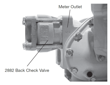
When ordering with a new metering system, a A2882 Back Check Valve comes mounted to the outlet side of the strainer housing, as shown in the figure. To complete the A2882 back check valve portion of the installation, connect a liquid line to the flange on the inlet side of the valve. The flange connection is 2-inch NPT.
Retrofit Installations
Depending on the existing configuration, it may be necessary to modify the outlet piping when adding an A2882 back check valve.
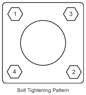
After relieving the internal pressure from the system, disconnect the outlet line from the outlet side of the strainer assembly. Then, connect the valve and flange assembly to the outlet side of the strainer. Use the four bolts and washers provided to fasten the valve/flange assembly to the strainer, tightening the bolts in a crossing pattern, as shown in the figure below. Once the valve/flange assembly is secure, connect the outlet line to the flange. The flange fitting is 2-inch NPT.
Item Numbers |
Refer to the illustrations in Bill of Materials for the item numbers given in these instructions. Item numbers appear in circles in the drawings. |
Disassembly
Follow these steps for disassembly:
1.Remove the valve from the line by removing the four screws (Item 3) and washers (Item 4) that hold it in place.
2.From the inlet side of the valve, unscrew the valve stem (Item 265) from the valve nut (Item 875).
3.Remove the valve nut (Item 875) by pressing down on the spring holder (Item 382). The spring should be held down with a press. Lift the valve nut out of position. Remove the spring holder and lock washer from the housing.
4.Remove the O-Ring retainer (Item 452), O-Ring (Item 470), piston (Item 133), O-Ring (Item 471), and spacer (Item 472), lifting by the threaded end of the valve stem (Item 265).
5.Remove the O-Ring retainer (Item 452) and O-Ring (Item 471) from the stem.
6.Remove the O-Ring (Item 471) and the piston (Item 133) from the stem.
7.Replace components, if necessary. Then reassemble. Since the bushing (Item 485) is pressed in place, it's not necessary to remove it.
Reassembly
Follow these steps for reassembly:
1.Place the piston (Item 133) on the valve stem (Item 265), with the raised rim pointing upwards.
2.Place the spacer (Item 472) and O-Ring (Item 471) on the piston (Item 133).
3.Place the O-Ring (Item 470) on the retainer (Item 452) and place it over the piston (Item 133) with the O-Ring downward.
4.Place a self-locking nut (Item 875) on the valve stem and tighten. Place a second self-locking nut (Item 875) on the valve stem and tighten.
5.Insert this assembly into the housing (Item 110) from the outlet side.
6.Place the compression spring (Item 595) over the valve stem (Item 265).
7.Insert the Teflon bearing (Item 486) into the valve spring holder (Item 382).
8.Place the spring holder (Item 382) on the housing (Item 110) and compress the spring inward. Use a press to overcome the force of the spring.
9.Secure the spring holder with the spiral retaining ring (Item 393).
The back check valve is now ready for reinstallation, using the four screws (Item 3) and washers (Item 4).