Liquid Controls meters are positive displacement meters. They are designed for liquid measurement in both custody-transfer and process-control applications. They can be installed in pump or gravity flow systems. Because of their simple design, they are easy to maintain, and easy to adapt to a variety of systems.
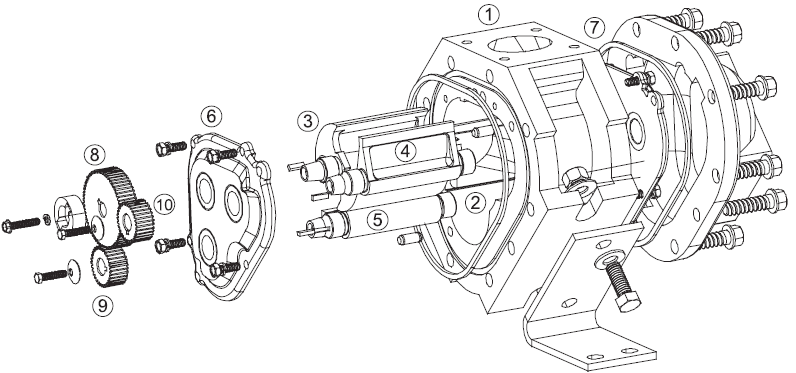
The meter housing (1) is designed with three cylindrical bores (2). Three rotors, the blocking rotor (3) and two displacement rotors (4, 5), turn in synchronized relationship within the bores. The three rotors are supported by bearing plates (6, 7). The ends of the rotors protrude through the bearing plates. The blocking rotor gear (8) is placed on the end of the blocking rotor. The displacement rotor gears (9, 10) are placed on the ends of the displacement rotors. These gears create the synchronized timed relationship between the three rotors.
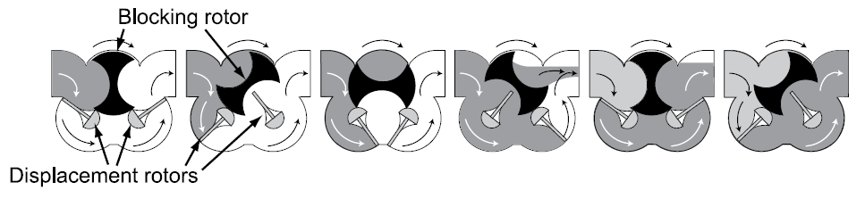
As fluid moves through the meter housing, the rotor assembly turns. The liquid is broken into uniform sections by the turning rotors. Fluid displacement occurs simultaneously. As fluid enters, another portion of the fluid is being partitioned and measured. At the same time, the fluid ahead of it is displaced out of the meter and into the discharge line. Since the volume of the bores is known, and the same amount of fluid passes through the meter during each revolution of the blocking rotor, the exact volume of liquid that has passed through the meter can be determined with a high degree of
accuracy.
This true rotary motion is transmitted through the packing gland, the face gear, the adjuster drive shaft, and the adjuster to the register stack and counter. True rotary motion output means consistent accuracy, since the register indication is in precise agreement with the actual volume throughput at any given instant. At any position in the cycle, the meter body, the blocking rotor, and at least one of the displacement rotors form a continuous capillary seal between the unmetered upstream product and the metered downstream product.
Because the product is separated by the capillary seal, no metal-to-metal contact is required within the metering element. This means no wear, and no wear means no increase in slippage, which means no deterioration in accuracy.
Throughout the metering element, the mating surfaces are either flat surfaces or cylindrical faces and sections that are accurately machined. These relatively simple machining operations, plus the fact that there is no oscillating or reciprocating motion within the device, permits extremely close and consistent tolerances within the LC meter.
The product flowing through the meter exerts a dynamic force that is at right angles to the faces of the displacement rotors. The meter is designed so that the rotor shafts are always in a horizontal plane. These two facts result in no axial thrust. Therefore, LC meters do not need thrust washers or thrust bearings, and the rotors automatically seek the center of the stream between the two bearing plates–eliminating wear between the ends of the rotors and the bearing plates. Once again, no wear results means no metal fatigue and no friction.
Liquid Controls meters are made of a variety of materials to suit a variety of products. Because of their no-wear design, capillary seals, and unique rotary metering, LC meters provide unequalled accuracy, long operating life, and exceptional dependability.