The Liquid Controls Pulse Output Device (POD) converts the rotary motion of the Liquid Controls Positive Displacement Flowmeter into electronic pulses. This allows the meter to interface with a wide variety of electronic monitoring devices and control equipment. The POD operates in standard and bidirectional flow applications.
Check Each Shipment |
Before installation, check your shipment against the packing list and ensure that no parts are missing. The packing list is inside the red information packet along with the Installation and Operation Manuals. |
The POD mounts directly to the front cover of any Liquid Controls meter in place of the packing gland. The motion of the meter’s blocking rotor is magnetically coupled through a stainless steel wall to the electronics compartment of the POD. This eliminates the dynamic seal of the packing gland and isolates the electronics from the process fluid in the meter.
Inside the electronics compartment, an optical shaft encoder converts the rotary motion into a high resolution, two-channel, quadrature square wave. Both outputs are driven by field effect transistors (FETs) and switch from zero volts in the “ON” state to the power supply voltage in the “OFF” state. As supplied from the factory, there is a 2.2KΩ pull-up resistor on each output which can be removed from the circuit in the field to produce a true “open drain” output. As open drain devices, the outputs can sink up to 100 mA in the “ON” state and sustain up to 30 VDC in the “OFF” state.
The electronics compartment also serves as a conduit junction box. The POD has an o-ring sealed, threaded cover. The standard wire entrance is a ½-14 NPT female hub which accepts threaded conduit or a cable gland. A screw-type, removable, terminal block on the circuit board facilitates wiring of the unit. With the wiring entrance sealed and the cover in place, the housing has a weatherproof rating of NEMA 4X.
POD Models
These are the available POD models:
•POD1 – Fork Drive with Buna-N O-Ring, 100 PPR Quad Pulser, 9 to 30VDC
•POD2 – Fork Drive with PTFE O-Ring, 100 PPR Quad Pulser, 9 to 30VDC
•POD3 – Blade Drive with Buna-N O-Ring, 100 PPR Quad Pulser, 9 to 30VDC
•POD4 – Blade Drive with PTFE O-Ring, 100 PPR Quad Pulser, 9 to 30VDC
•POD5 – Fork Drive with Buna-N O-Ring, 100 PPR Quad Pulser, 5 to 24VDC, POD5 is not IECEx approved
•POD6 – Fork Drive with EPDM O-Ring, 100 POD7 PPR Quad Pulser, 9 to 30VDC
•POD7 – BLADE DRIVE WITH EPDM O-RING, 100 PPR Quad Pulser, 9 to 30VDC
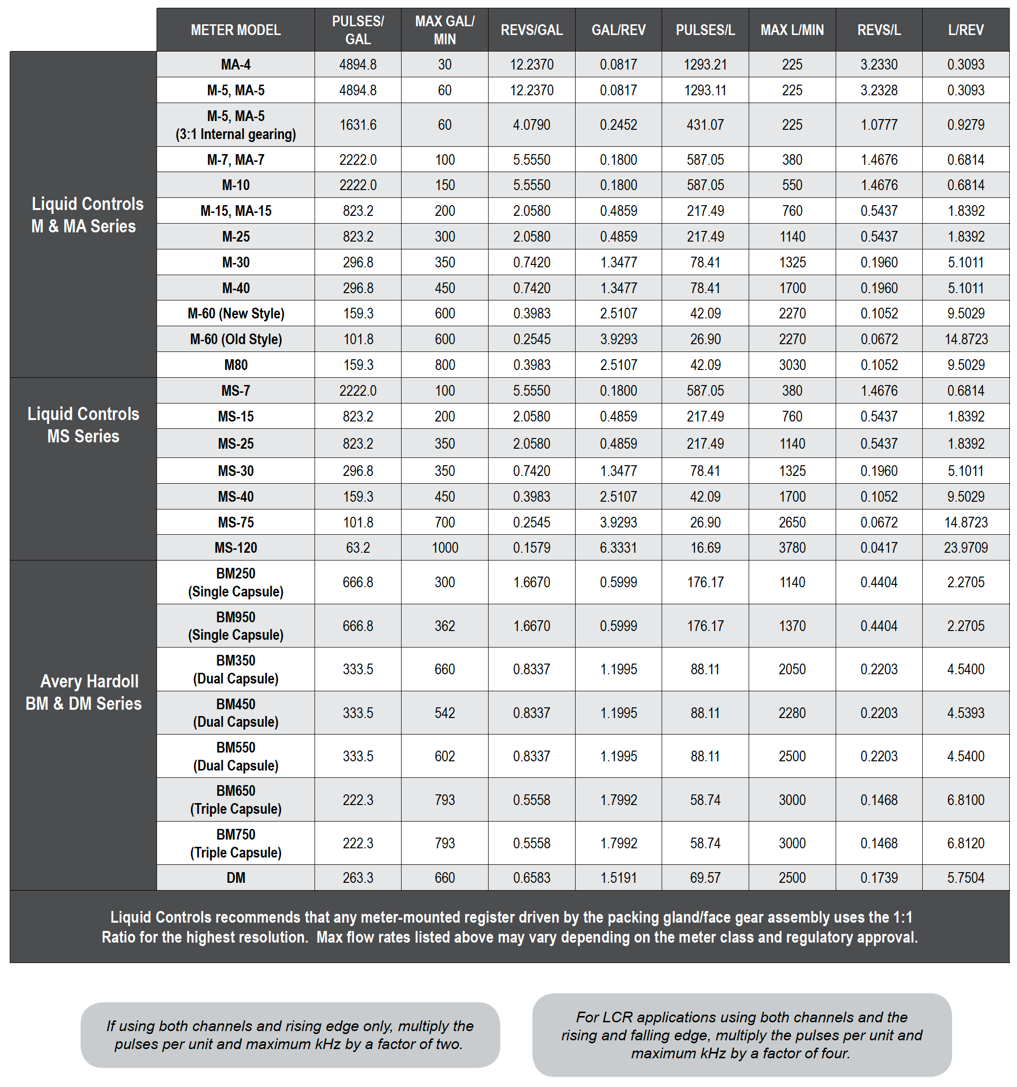
Output Signal Resolutions
Approximate K-Factors and Volumetic Reference Data
When initially calibrating a specific meter model, the K-Factor (Pulses/Unit) values given below are for reference only and are not to be used as a final K-Factor. NOTE: ll Liquid Controls meter models listed below assume use of the 400ppr pulser with a 1:1 Packing Gland/Face Gear ratio when calculating the Pulses/Unit. For 2:1 ratio, divide the Pulses/Unit by 2.