The Liquid Controls Optical Vapor Eliminator (A8302) is designed for use with LectroCount® electronic registers and require the use of a solenoid-operated valve. It is constructed to be used with Liquid Controls MA5 and MA7 meters measuring liquid propane gas. Because it is designed with the same mounting dimensions as Liquid Controls mechanical vapor eliminators, the optical vapor eliminator requires minimal plumbing changes in order to retrofit to existing meter installations of the same application. Electronic registers require CPU board part number 81920 for LCR and LCR-II; CPU board part number 81924 for LC³.
NOTICE |
A8302 LPG metering systems use materials specifically intended for their application to ensure high performance, longevity and above all safety. Under no circumstances should a system designed for LPG be used to deliver another product without first replacing the necessary metallurgical and seal materials specified for the application. Conversion kits are available from Liquid Controls. |
How the Optical Vapor Eliminator Works
The Liquid Controls Optical Vapor Eliminator removes vapor from the metering system. Removing the vapor from the metering system ensures that only liquid can pass through the meter for measurement.
An optical sensor, installed in the wall of the vapor eliminator housing, activates and deactivates a solenoid valve (S3) located at the top of the vapor eliminator.
A solenoid valve, located at the top of the vapor eliminator, is either open or closed.
|
|
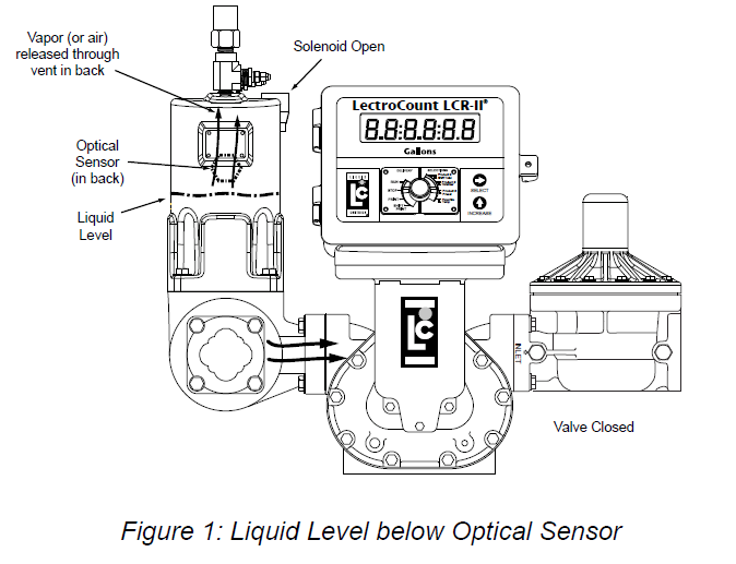
When the liquid level is below the optical sensor (and a delivery is initiated) the solenoid valve opens to vent vapor to a supply or storage tank (Figure 2). At the same time, the electronically acuated control valve, located at the meter outlet, closes to stop the flow of product.
|
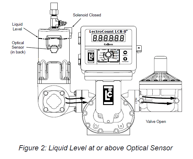 |
As long as a delivery is active and the liquid level remains at or above the optical sensor, the optical vapor eliminator solenoid valve remains closed and the control valve remains open. If the liquid level should drop below the optical sensor, the optical vapor eliminator solenoid valve opens vent the vapor, and the outlet control valve closes blocking product flow.
When the delivery is complete, both the outlet control valve and the optical vapor eliminator solenoid valve close until activated for a new delivery.
The figures to the right show a cutaway view of the vent port through the solenoid valve. This port has been designed to optimize the venting of vapor from the eliminator.
When the liquid level is below the sensor, the S3 solenoid valve opens and allows vapor to vent through the solenoid valve, as shown in Figure 3.
|
 |
When the liquid level is at or above the optical sensor, the S3 solenoid valve closes the vent path, as shown in Figure 4.
|
 |
The diagram in Figure 5 shows the Lectro-Count register logic for a preset delivery. In order to function properly, the optical vapor eliminator must be used together with a solenoid-actuated control valve at the meter outlet.
