The Liquid Controls Optical Air Eliminator is designed for use with LectroCount® Electronic Registers. With placement in the wall of the air eliminator housing, an optical sensor monitors the liquid level. The presence or absence of liquid at the sensor level activates or deactivates a solenoid valve located at the top of the air eliminator to vent air or vapor from the system.
The optical air eliminator is designed to work with Liquid Controls M5, M7, M10, M15, and M25 meters, for applications measuring refined petroleum products. Designed with the same mounting dimensions as Liquid Controls mechanical air eliminators, the optical air eliminator does not require plumbing changes to retrofit to existing meter installations. However, electronic registers do require CPU board part number 81920 for LCR and LCR-II, or CPU board part number 81924 for LC³. The optical air eliminator also requires the use of a solenoid-operated control valve, such as the E-7 or A2848-11, on the outlet side of the meter.
Class 2
The Liquid Controls Optical Air Eliminator can be manufactured for Class 2 aviation applications. The Class 2 optical air eliminator (Part #A8981A) is made with an anodized aluminum housing and a stainless steel solenoid valve.
How the Optical Air Eliminator Works
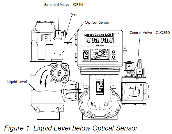
A solenoid valve, located at the top of the air eliminator, is either open or closed. When the liquid level is below the optical sensor (Figure 1), and a delivery is initiated, the solenoid valve opens and vents air and vapor to atmospheric pressure. At the same time, a solenoid-actuated control valve (A2982-11 or A2848-11) closes at the meter outlet.
|
|
When liquid rises to the optical sensor level and the air is exhausted (Figure 2), the optical air eliminator solenoid valve closes and prevents continued venting to atmospheric pressure. At the same instant, the control valve at the meter outlet opens so that a delivery may begin or continue. This functionality ensures that only liquid passes through the meter for measurement. |
 |
As long as a delivery is active and the liquid level remains at or above the optical sensor, the optical air eliminator solenoid valve remains closed and the control valve remains open. If the liquid level should drop below the optical sensor, the optical air eliminator solenoid valve opens and the control valve closes. When the delivery is complete, the control valve closes and the printer prints a delivery ticket. The optical air eliminator solenoid valve is not active between deliveries and remains OFF or closed.
The figures to the right show a cutaway view of the vent port through the solenoid valve. This port has been designed to optimize the venting of air and vapor from the optical air eliminator.
When the liquid level is below the sensor, the S3 solenoid valve is open and allows air and vapor to vent through the solenoid valve as shown in Figure 3. |
 |
When the liquid level is at or above the optical sensor, the S3 solenoid valve closes the vent path as shown in Figure 4.
|
 |
The diagram in Figure 5 shows the Lectro-Count register logic for a preset delivery. In order to function properly, the optical air eliminator must be used together with a solenoid-actuated control valve at the meter outlet, such as the A2982-11 or A2848-11.
