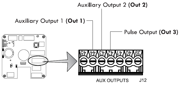
The LCR-II provides three open-drain transistor auxiliary outputs for different external devices–such as pump controls and additive injectors. The schematic to the right identifies the J13 terminals where the auxiliary outputs can be connected to the LCR-II.
Disconnect Power |
Disconnect the power before working on the CPU board. |
Auxiliary Output 1 (Out 1)
This signal has four output settings: Off, On, On During Delivery, and Monitor Flowrate.
Auxiliary Output 2 (Out 2)
This signal has three output settings: Off, On, On During Delivery, and Flow Direction.
Pulse Output (Out 3)
This output represents the gross delivery quantity for uncompensated deliveries or the net delivery quantity (for compensated deliveries). This output is a real time 50/50 duty cycle representing the least significant digit of the LCR-II totalizers.
Auxiliary Output Settings |
To select the Auxiliary Output settings, refer to the LectroCount LCR-II Setup and Operation manual. |